Radiating structure and molding method thereof

A technology of heat dissipation structure and molding method, applied in the cooling of instruments, parts of instruments, instruments, etc., can solve the problems of long processing time, unsuitable production rate, and inability to form penetrating through-hole structures, etc., to achieve improved air cooling efficiency effect

Inactive Publication Date: 2011-08-17
MITAC PRECISION TECH CO LTD SHUNDE DISTRICT FOSHAN CITY
View PDF0 Cites 1 Cited by
  • Summary
  • Abstract
  • Description
  • Claims
  • Application Information

AI Technical Summary

Problems solved by technology

[0005] However, extrusion molding can only produce a continuous structure with a single cross-sectional shape. If the travel direction of the member passing through the die mouth of the mold is the long axis direction, the extrusion molding cannot form a penetrating structure perpendicular to the long axis direction. through-hole structure
If the ventilation hole is to be made through additional processing, since the heat dissipation structure 1 has protruding fins, the protruding fins 3 will cause the punching device to be unable to punch holes on the substrate 2
Tapping the substrate 2 with a drill bit can only complete one vent hole per process, especially when the heat dissipation structure 1 must be densely covered with vent holes, tapping holes with a drill bit will consume a lot of processing time, which does not meet the requirements of productivity
Therefore, the closed casing with an extruded heat dissipation structure can only introduce cooling air into the casing and discharge hot air through the vent holes on the front and rear panels. It is difficult to further strengthen the circulation of cooling air to improve the air cooling effect

Method used


Image

  • Radiating structure and molding method thereof
  • Radiating structure and molding method thereof
  • Radiating structure and molding method thereof

Examples


Embodiment Construction

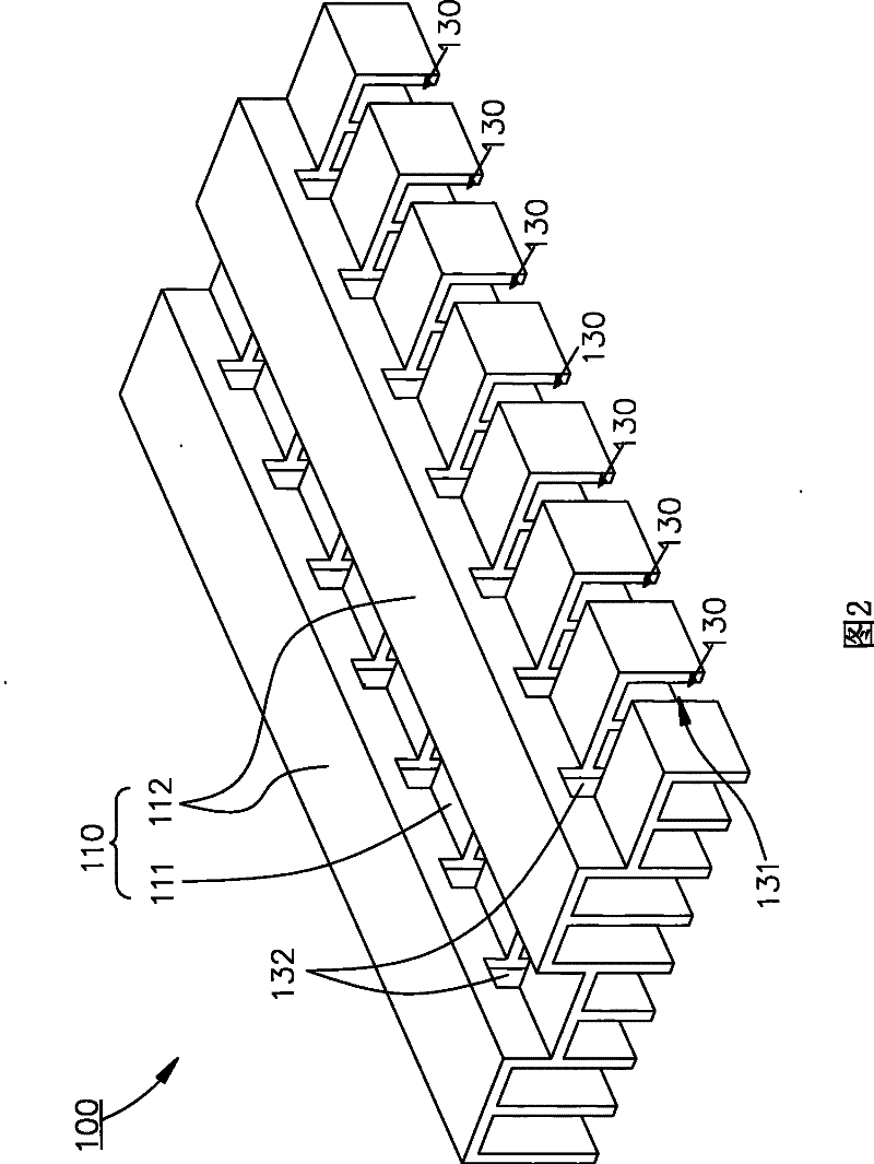
[0029] refer to figure 2 , image 3 ,and Figure 4 As shown, it is a heat dissipation structure 100 disclosed in the first embodiment of the present invention, which includes an extruded part 110 and a plurality of fins 120. The extruded part 110 and the fins 120 are integrally formed, and the cooling air can pass through The shape part 110 improves the air cooling effect.

[0030] Figure 5A for image 3 and Figure 4 Schematic cross-section along A-A'. The extruded part 110 is a single piece made by extrusion process, or a tubular structure formed around the plate. The extruded part 110 has a plurality of bending parts 111 and a plurality of connecting parts 112 extending along a long axis direction alternately. The connecting portion 112 is used for connecting adjacent bent portions 111 , and the bent portion 111 protrudes from the surface of the extruded part 110 . Due to the characteristics of the extrusion process, the bent portions 111 extend along the long axi...


PUM


Abstract

The invention relates to a radiating structure and a molding method thereof. An extruded piece is manufactured through extruding and molding, and the extruded piece is provided with a plurality of bending parts which are extended along the same direction and outwards protruded, and in the processes of extruding and molding, fins are further formed on the bending parts. The fins and the extruded piece are cut by a cutter so as to form cutting channels, wherein the cutter is firstly used for cutting the fins to form notches and then the bending parts to form cutting through holes, the notches and the cutting through holes form the cutting channels, and the cutting through holes are used for allowing air to flow through both sides of the extruded piece through the cutting through holes. By cutting the bending parts by the cutter, a large quantity of the cutting through holes can be quickly formed on the extruded piece without being influenced by the fins so as to improve air cooling and radiating effects.

Description

technical field [0001] The invention relates to a heat dissipation structure, in particular to an extruded heat dissipation structure for enhancing air cooling and heat dissipation. Background technique [0002] refer to Figure 1A and Figure 1B Shown is the air-cooling heat dissipation structure 1 in the known technology. The air cooling structure 1 mainly includes a substrate 2 and fins 3 formed on the substrate 2 . The substrate 2 is used to contact a heat source, or used as a shell to cover the heating element. The inner surface of the substrate 2 absorbs the heat from the heat source 4 or the heating element 5 through contact heat conduction or convective heat transfer, while the outer surface exchanges heat with air to dissipate heat by convective heat transfer. The fins 3 are arranged parallel to the outer surface of the base plate 2 to increase the overall heat exchange area and enhance convective heat transfer efficiency. [0003] The traditional manufacturing ...

Claims


Application Information

Patent Timeline
Patent Type & Authority Patents(China)
IPC IPC(8): G12B15/06G12B15/04
Inventor 梁庭威吴敏瑞
Owner MITAC PRECISION TECH CO LTD SHUNDE DISTRICT FOSHAN CITY
Why Eureka
Try Eureka