
Injection mould

An injection mold and injection molding technology, applied in the field of injection molds, can solve the problems of mold temperature rise, extension of demolding time, slow product molding, etc., to slow down temperature rise, increase surface area, and improve efficiency.

Inactive Publication Date: 2015-04-01
常熟市古里镇淼泉浩军金属模具厂
View PDF4 Cites 1 Cited by
  • Summary
  • Abstract
  • Description
  • Claims
  • Application Information

AI Technical Summary

Problems solved by technology

During the continuous processing of the injection mold, the injected plastic is continuously heated, and the temperature of the mold rises. Due to poor heat dissipation, it is easy to cause slow molding of the product and prolong the demoulding time. The product is deformed during the demoulding process, resulting in scrap
The general method adopted is to pass cooling water through the mold for cooling, which requires a large amount of cooling water, and the cooling water is continuously heated when it is recycled, and the efficiency of repeated cooling is poor. It is necessary to install a large cooling water pool or tower, which is costly.

Method used


Image

  • Injection mould

Examples


Embodiment Construction

[0013] The following will clearly and completely describe the technical solutions in the embodiments of the present invention. Obviously, the described embodiments are only some of the embodiments of the present invention, rather than all the embodiments. Based on the embodiments of the present invention, all other embodiments obtained by persons of ordinary skill in the art without making creative efforts belong to the protection scope of the present invention.

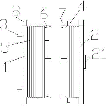
[0014] see figure 1 , the embodiment of the present invention includes:

[0015] An injection mold, comprising: an injection movable mold 1 and an injection fixed mold 2 corresponding to the injection movable mold 1, the fixed injection mold 1 and the injection fixed mold 2 are respectively provided with a fixing plate 8, which is convenient for installation and fixing on an injection molding machine Above, the injection movable mold 1 and the injection fixed mold 2 are square modules respectively, and heat dissipat...


PUM


Abstract

The invention discloses an injection mould which comprises a moving injection mould and a fixed injection mould corresponding to the moving injection mould, wherein the moving injection mould and the fixed injection mould are respectively provided with fixed plates; the moving injection mould and the fixed injection mould are square moulds, radiating grooves are respectively formed on four faces around the square moulds, a first cooling water pipe is connected to the back face of the moving injection mould, and a second cooling water pipe is arranged on the top of the fixed injection mould. Through the manner, the injection mould disclosed by the invention increases the surface areas of the moving injection mould and the fixed injection mould by virtue of the radiating grooves, so that the efficiency of air-cooling radiation is improved, temperature rise of the mould is effectively alleviated, the use level of cooling water is reduced, and the production cost is lowered.

Description

technical field [0001] The invention relates to the field of mold design, in particular to an injection mold. Background technique [0002] Plastic parts such as bottle caps and remote control shells are generally produced using injection molds. The injection mold consists of a moving mold and a fixed mold. The moving mold is installed on the moving template of the injection molding machine, and the fixed mold is installed on the injection molding machine fixed on the template. During injection molding, the movable mold and the fixed mold are closed to form the gating system and the cavity. When the mold is opened, the movable mold and the fixed mold are separated, and then the plastic product is taken out. [0003] Although the structure of the mold may vary due to the variety and performance of the plastic, the shape and structure of the plastic product, and the type of the injection machine, the basic structure is the same. During the continuous processing of the inject...

Claims


Application Information

Patent Timeline
Patent Type & Authority Applications(China)
IPC IPC(8): B29C45/73B29C45/26
CPCB29C45/7337B29C45/2602
Inventor 王浩军
Owner 常熟市古里镇淼泉浩军金属模具厂
Learn More