Air-cooling heat dissipation installation structure of motor controller

A technology of motor controller and heat dissipation structure, which is applied in the construction parts of electrical equipment, cooling/ventilation/heating transformation, housing with display/control unit, etc., which can solve the problems of low wind energy utilization efficiency, complex heat dissipation structure, and space occupation Large and other problems, to achieve the effect of improving the efficiency of air cooling and heat dissipation, the overall structure is simple, and the sealing is reliable

Pending Publication Date: 2022-03-25
徐州尚恒工控技术有限公司
View PDF1 Cites 1 Cited by
  • Summary
  • Abstract
  • Description
  • Claims
  • Application Information

AI Technical Summary

Problems solved by technology

[0005] First, the wind expelled by the fan of the air-cooled heat dissipation structure blows through the heat sink to realize the heat dissipation of the controller, and its heat dissipation performance is directly related to the air output of the fan. low efficiency;
[0006] Second, multiple air ducts bypass the controller, the heat dissipation structure is complex, and it takes up a lot of space, making installation difficult

Method used


Image

  • Air-cooling heat dissipation installation structure of motor controller
  • Air-cooling heat dissipation installation structure of motor controller
  • Air-cooling heat dissipation installation structure of motor controller

Examples


Embodiment Construction

[0022] The following will clearly and completely describe the technical solutions in the embodiments of the present invention with reference to the accompanying drawings in the embodiments of the present invention. Obviously, the described embodiments are only some, not all, embodiments of the present invention. Based on the embodiments of the present invention, all other embodiments obtained by persons of ordinary skill in the art without making creative efforts belong to the protection scope of the present invention.

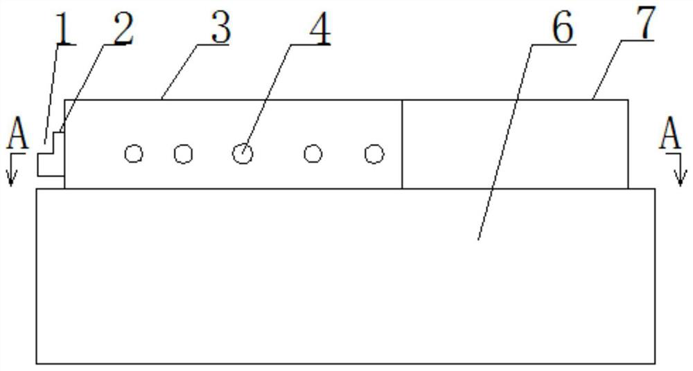
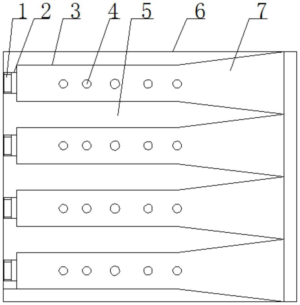
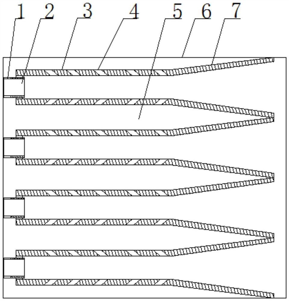
[0023] Such as Figure 1 to Figure 4 As shown, an air-cooled and heat-dissipating installation structure of a motor controller includes a controller housing 6 . A row of parallel cooling pipes 3 is fixed on the upper side of the controller housing 6 . The heat dissipation pipe 3 adopts a square pipe, and the heat dissipation pipe 3 is attached to the upper side of the controller housing 6 and fixedly connected by welding. The front end of the heat dissipatio...


PUM


Abstract

The invention discloses a motor controller air cooling heat dissipation installation structure, and belongs to the technical field of electric vehicles. Comprising a controller shell, and a row of parallel heat dissipation pipes are fixed to one side face of the controller shell; the radiating pipes are square pipes, convection gaps are reserved between the adjacent radiating pipes, and inclined convection holes which are evenly distributed are formed in the two side faces and the upper side face of each radiating pipe. The front end of the radiating pipe is connected with an air inlet pipe, and the end part of the air inlet pipe is provided with a semi-cylindrical lower spigot; the rear ends of the radiating pipes are provided with outward-extending horn mouths, and the opening edges of the horn mouths of the adjacent radiating pipes are connected. The overall structure is simple, installation is rapid, dismounting is easy, the rear end of the heat dissipation pipe is provided with the outward-extending horn mouth, the air outlet efficiency is improved, the convection effect is improved through the air outlet pressure difference, external free air enters the heat dissipation pipe through the inclined convection holes, the air volume entering the heat dissipation pipe is larger than the air volume of a draught fan, and therefore the air volume is increased, and the heat dissipation efficiency is improved. And the air-cooling heat dissipation efficiency is improved.

Description

technical field [0001] The invention relates to the technical field of electric vehicles, in particular to an air-cooled and heat-dissipating installation structure for a motor controller. Background technique [0002] Electric vehicles are powered and controlled by the electric drive system. As the core components of the electric drive system, the drive controller and DC converter play a key role in the performance of electric vehicles. Among them, the drive controller is mainly used to drive and control the operation of the motor, and the DC converter is mainly used to provide electric energy for the low-voltage electrical equipment of the vehicle and charge the auxiliary power supply. At present, the electric vehicle drive controller will generate a large amount of heat when it is working, and it needs to be dissipated by setting up a radiator, usually through a cooling fan for air cooling. [0003] China discloses a motor controller with good heat dissipation performanc...

Claims


Application Information

Patent Timeline
Patent Type & Authority Applications(China)
IPC IPC(8): H05K7/20H05K5/00
CPCH05K7/20145H05K7/20172H05K5/0017
Inventor 唐俊涛任义杰任永
Owner 徐州尚恒工控技术有限公司
Why Eureka
Try Eureka