
Electrostatic defending device of multiple discharge paths

A discharge path and electrostatic protection technology, applied in the direction of static electricity, electrical components, etc., can solve problems such as carbonization, tip oxidation, and deterioration, and achieve the effect of improving service life and increasing the probability of success

Inactive Publication Date: 2010-03-03
MITAC PRECISION TECH CO LTD SHUNDE DISTRICT FOSHAN CITY
View PDF0 Cites 2 Cited by
  • Summary
  • Abstract
  • Description
  • Claims
  • Application Information

AI Technical Summary

Problems solved by technology

[0003] However, in the prior art, the method of using tip discharge to induce electrostatic discharge to dissipate the electrostatic current often fails to induce discharge in actual operation.
The reasons can be roughly classified as: (1) Improper configuration of the distance between the tips of the two conductors; (2) Other discharge paths appear: the electrostatic arc usually does not follow a straight line, but is located within a three-dimensional space in front of the conductor tip, within a specific distance, as long as there are other (3) continuous discharge for many times; (4) after the conductor tip is discharged many times, the tip part will be oxidized or carbonized, resulting in the tip becoming round and causing the discharge effect to deteriorate.

Method used


Image

  • Electrostatic defending device of multiple discharge paths
  • Electrostatic defending device of multiple discharge paths
  • Electrostatic defending device of multiple discharge paths

Examples


Embodiment Construction

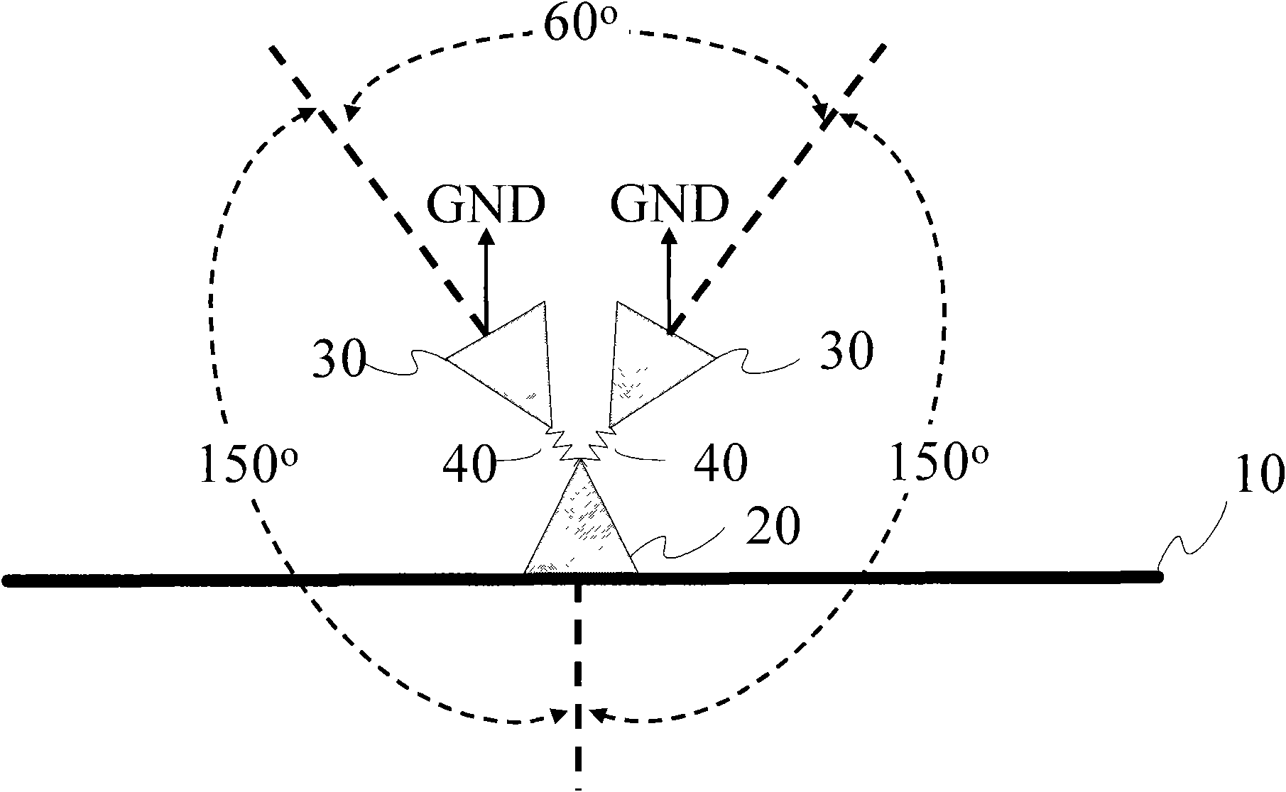
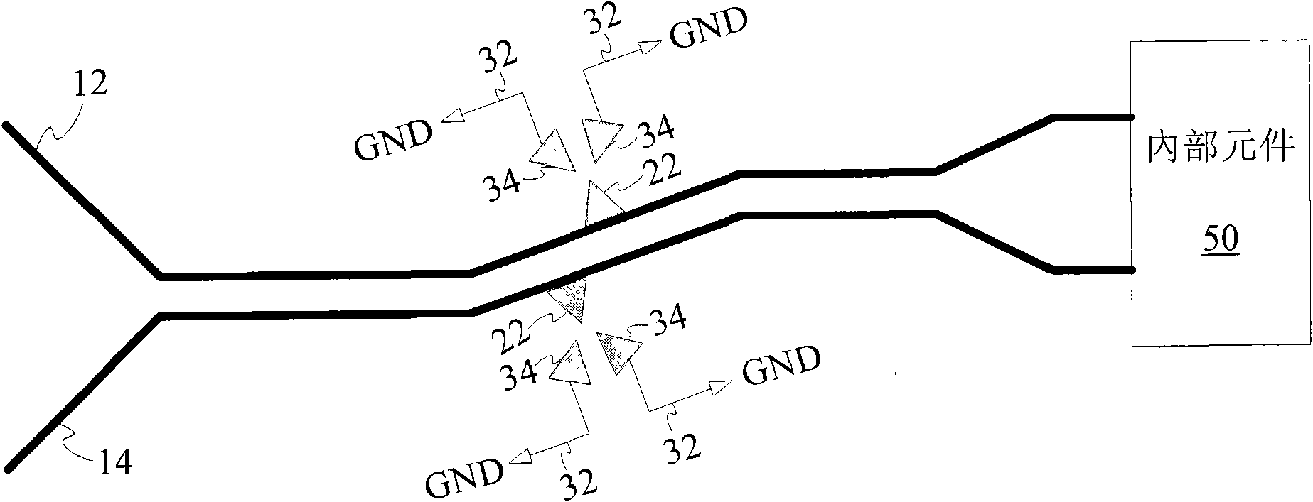
[0012] Please refer to figure 1 , which is a schematic diagram of the first embodiment of an electrostatic protection device with multiple discharge paths. The electrostatic protection device with multiple discharge paths includes: a wire 10 , a discharge part 20 , and a ground part 30 .

[0013] The wire 10 is used to transmit data, current, voltage, etc. in a general circuit, and static electricity is also conducted through the wire 10 . Therefore, the conductive wire 10 provides electrostatic current to pass through, and because a sudden static electricity may be generated on the conductive wire 10 in an instant, the discharge part 20 can be provided on the conductive wire 10 where electrostatic discharge may occur.

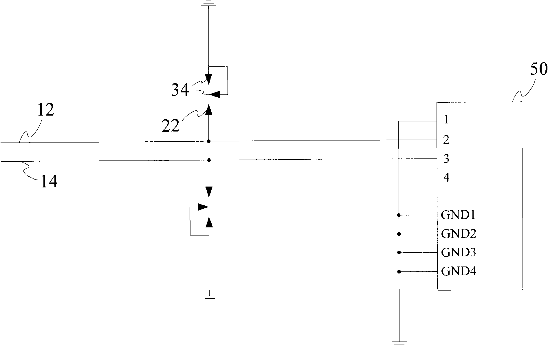
[0014] The discharge portion 20 is coupled to the wire 10 , and a plurality of ground portions 30 are disposed around the discharge portion 10 . A discharge path 40 is formed between each ground portion 30 and the discharge portion 20 to provide electrostati...


PUM


Abstract

The invention relates to an electrostatic defending device of multiple discharge paths. The electrostatic defending device comprises a conducting wire, a discharge part and a plurality of grounding parts, wherein the conducting wire is used for providing electrostatic current to pass through; the discharge part is coupled to the conducting wire; the grounding parts surround the discharge part, anda discharge path is respectively formed between each grounding part and the discharge part for providing electrostatic discharge; and distances of all discharge paths are equal. When the discharge paths are increased, the success probability of inducing the electrostatic discharge is improved so as to ensure that the electrostatic current is easier to dissipate by a plurality of the discharge paths, and the service life of a discharge point and a grounding point is further improved.

Description

technical field [0001] The invention relates to an electrostatic protection device, in particular to an electrostatic protection device with multiple discharge paths. Background technique [0002] Electro Static Discharge (ESD) is one of the main causes of damage to most electronic components or electronic systems, and this kind of electrostatic damage can cause damage to semiconductor components, thereby affecting the function of integrated circuits and making electronic products useless. Traditionally, devices that discharge static electricity are mostly implemented using the principle of tip discharge. The electronic device adopts the electrostatic protection method of tip discharge. The current leads to the grounding position in the device to prevent electrostatic sensitive components or microcircuits from being damaged by static electricity and failing. [0003] However, in the prior art, the tip discharge is used to induce electrostatic discharge to dissipate the elec...

Claims


Application Information

Patent Timeline
Patent Type & Authority Applications(China)
IPC IPC(8): H05F3/00H05F3/02H05F3/04
Inventor 施鸿荣林达远
Owner MITAC PRECISION TECH CO LTD SHUNDE DISTRICT FOSHAN CITY
Learn More