
Intelligent skipping method

A smart, layer-jumping technology, applied in optical recording/reproducing, data recording, instruments, etc., can solve the problems of focusing failure, difficult focusing, and taking a long time.

Inactive Publication Date: 2005-12-14
LITE ON TECH CORP
View PDF0 Cites 1 Cited by
  • Summary
  • Abstract
  • Description
  • Claims
  • Application Information

AI Technical Summary

Problems solved by technology

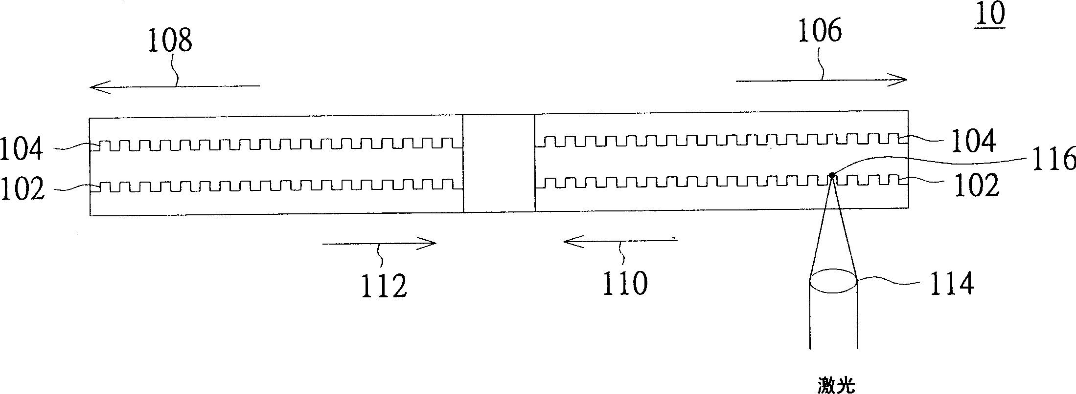
Therefore, it is very likely that the focus point 116 falls between the reflective layer 102 and the reflective layer 104 during layer jumping due to difficulty in focusing, or exceeds the top of the reflective layer 104 to cause focusing failure, which is detected by the optical pickup head at this time. The focus error signals are all 0
In this case, even the focus compensation technology may not help, and because the position of the objective lens 114 is often not known after the layer jump fails, the focusing procedure has to be restarted, resulting in a longer time for refocusing , reducing the efficiency of data access

Method used


Image

  • Intelligent skipping method
  • Intelligent skipping method
  • Intelligent skipping method

Examples


Embodiment Construction

[0024] Because the conventional layer-jump method is prone to focus failure after the layer-jump when the outer track of the disc is at a high speed, the purpose of the present invention is to solve the above problems. A preferred embodiment is described as follows.

[0025] Please also refer to Figure 4 to Figure 6 , Figure 4 Show and illustrate the flow of the intelligent layer-jumping method according to a preferred embodiment of the present invention; Figure 5 A schematic diagram illustrating the first layer-jumping process on the disc according to the intelligent layer-jumping method according to a preferred embodiment of the present invention; Image 6 A schematic diagram illustrating the second layer-jumping process on the disc according to the intelligent layer-jumping method according to a preferred embodiment of the present invention is shown.

[0026] The intelligent layer jumping method of the preferred embodiment of the present invention is applied to an opti...


PUM


Abstract

The intelligent layer jump method is applied in reading out CD in a CD driver. The CD has central reference point, at least one first reflecting layer and one second reflecting layer. The first reflecting layer has several first tracks, and the second reflecting layer has several second tracks. The intelligent layer jump method includes: focusing the laser beam of the CD driver onto the s reflecting layer to form the first focus and obtain one starting position; comparing the starting position and the target position on the second reflecting layer to decide the layer jump and track seeking path of the focus; and shifting the focus from the starting position to the target position according to the set layer jump and track seeking path.

Description

technical field [0001] The present invention relates to an intelligent layer-jumping method, and in particular relates to an intelligent layer-jumping method applied to CD drives. Background technique [0002] With the increasing demand for high-capacity optical storage media, a digital versatile disc (Digital Versatile Disc, hereinafter referred to as a DVD disc) with more than two reflective layers has increasingly played an important role. Therefore, when reading a DVD disc, how to quickly and stably read the data on the disc to reduce the data access time (data access time) is a research topic that various manufacturers are devoting themselves to. [0003] An optical disc drive rotates a disc and moves an optical pick-up head in the radial direction of the disc, and then uses a laser beam to scan the reflective layer of the disc to access data. Please refer to FIG. 1 , which shows a schematic cross-sectional view of a conventional disk with double-layer reflective layer...

Claims


Application Information

Patent Timeline
Patent Type & Authority Applications(China)
IPC IPC(8): G11B7/005
Inventor 许世昌赖志名黄伯臻乔执中
Owner LITE ON TECH CORP
Learn More