Combined hot pan energy-saving device

An energy-saving device and combined technology, applied in the direction of the shell/sleeve of the cooker, can solve the problems of energy consumption, staff discomfort, prolonged cooking time, etc., to achieve simple and fast assembly and disassembly, and shorten the cooking time. Effect of heating time and energy consumption reduction

Inactive Publication Date: 2010-03-10
方赞堂
View PDF0 Cites 3 Cited by
  • Summary
  • Abstract
  • Description
  • Claims
  • Application Information

AI Technical Summary

Problems solved by technology

[0002] At present, the most common cooking method is usually to place the cooking pot on a heating device (such as a gas stove, an induction cooker or a vaporizer...etc.) During the cooking process, some heat will be transferred outward through the pot wall, and the heat will be absorbed by the surrounding air and lost in the air, resulting in longer cooking time and more energy consumption.
Furthermore, if there are a plurality of cooking pots cooking at the same time, the problem of the heat dissipating outwards in the surrounding air will be more serious, and the heat dissipating outwards will also cause the temperature of the cooking environment to rise significantly, so that the working environment Too stuffy and causing extreme discomfort to staff
[0003] Furthermore, the above-mentioned problems will become more obvious as the ambient temperature changes. When cooking food in severe cold regions, since the heat of the cooking pot is continuously absorbed by the surrounding cold air, it will not only take longer to cook, In addition, the carbon generated in the cooking process and the energy consumption will be relatively more serious. For the current environment where energy saving and carbon reduction are taken as the premise of environmental protection everywhere, it is really a very serious problem.

Method used


Image

  • Combined hot pan energy-saving device
  • Combined hot pan energy-saving device
  • Combined hot pan energy-saving device

Examples


Embodiment Construction

[0026] With regard to the inventor's technical means, a preferred embodiment will be described in detail below in conjunction with the drawings, so as to provide an in-depth understanding and recognition of the present invention.

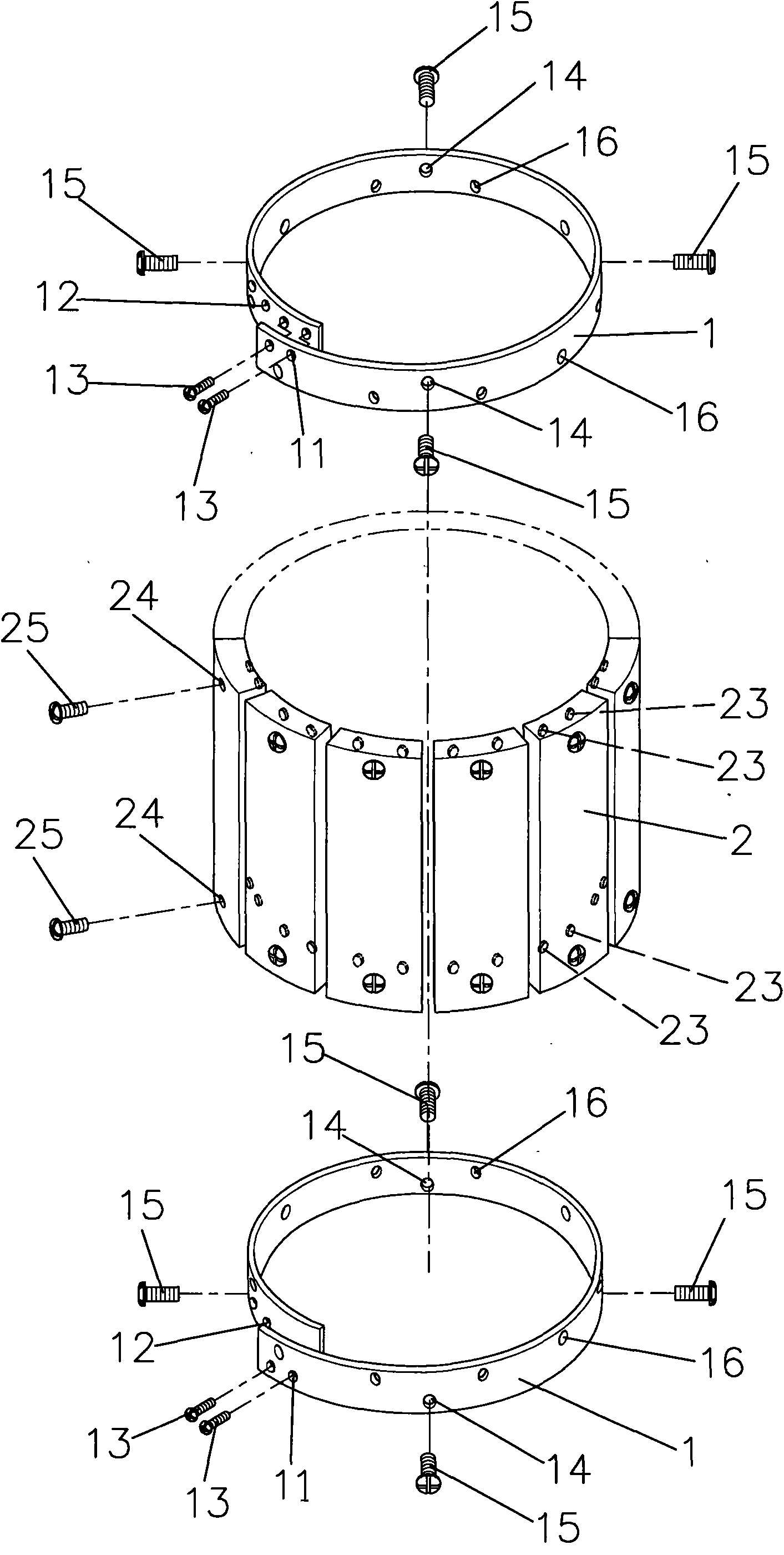
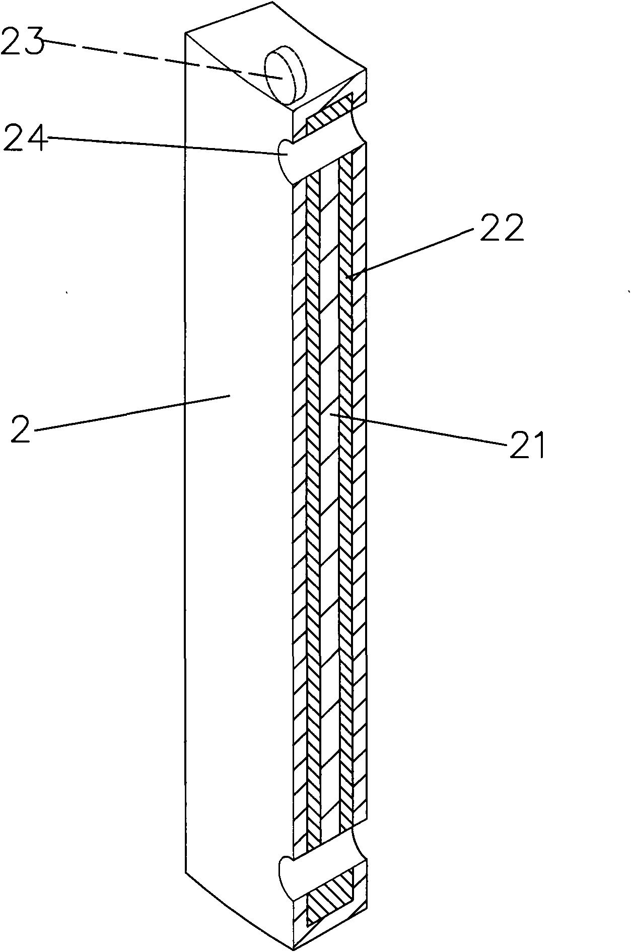
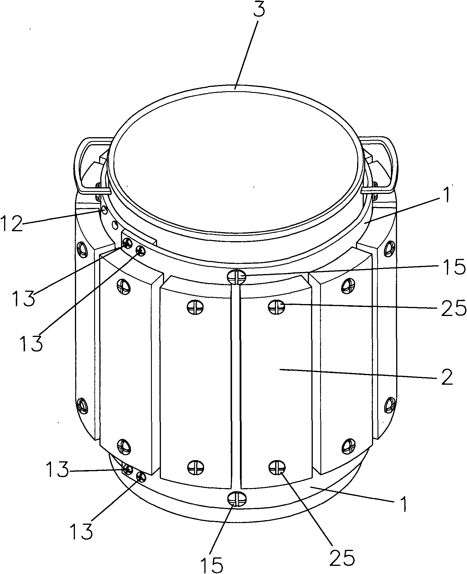
[0027] See first figure 1 , figure 2 As shown, the preferred embodiment of the present invention mainly includes a pair of fixing rings 1 and at least two energy-saving panels 2, wherein:

[0028] The pair of fixed rings 1 is a strip made of metal material (preferably magnetic stainless steel), such as figure 1 As shown, one end of the belt-shaped body is provided with a locking hole 11, and the other end is provided with a plurality of adjustment holes 12. The locking holes 11 can correspond to the adjustment holes 12 and are pierced by locking elements 13. Locking to form a fixed ring 1, the fixed ring 1 is provided with a plurality of through holes 14, the through holes 14 can be used for the locking element 15 to pass through, and the fixed r...


PUM


Abstract

The invention discloses a combined hot pan energy-saving device, which comprises fixed rings and at least two energy-saving plates; the fixed rings are made of metal and provided with a plurality of through holes which are inserted with locking and connecting elements; the energy-saving plates are provided with metal shells, filled with a heat insulating material inside, and fixed at the peripheryof the fixed rings; the pair of fixed rings can adjust the looping size so as to be fixed on the outer walls of saucepans with different calibers; and the energy-saving plates have heat insulating function, and can be fixed on the outer sides of the fixed rings to form an encircling state. The design of the energy-saving plates coated at the periphery of a saucepan ensures that the heat in the heating process is concentrated inside the energy-saving plates to avoid the heat being transferred outward and lost, so the combined hot pan energy-saving device can shorten the heating time and has the effect of saving energy.

Description

technical field [0001] The invention relates to an energy-saving device which is fixed on the outer wall of a cooking pot to prevent heat from being transferred and lost, and has the ability to shorten cooking time and save energy. Background technique [0002] At present, the most common cooking method is usually to place the cooking pot on a heating device (such as a gas stove, an induction cooker or a vaporizer...etc.) During the cooking process, some heat will be transferred outward through the wall of the cooking pot, and the heat will be absorbed by the surrounding air and lost in the air, resulting in longer cooking time and more energy consumption. Furthermore, if there are a plurality of cooking pots cooking at the same time, the problem of the heat dissipating outwards in the surrounding air will be more serious, and the heat dissipating outwards will also cause the temperature of the cooking environment to rise significantly, so that the working environment It is...

Claims


Application Information

Patent Timeline
Patent Type & Authority Applications(China)
IPC IPC(8): A47J36/36
Inventor 方赞堂
Owner 方赞堂
Why Eureka
Try Eureka