Eureka AIR delivers breakthrough ideas for toughest innovation challenges, trusted by R&D personnel around the world.

Synchronous centering and positioning device

A technology for centering positioning and fixing shafts, which is applied in positioning devices, workpiece clamping devices, clamping, etc., and can solve problems such as difficulty in fixing the same workpiece at the same position, unreliable processing quality of workpieces, inaccurate repeated positioning, etc. , to achieve the effect of eliminating asynchronous defects, compact structure and convenient operation

Inactive Publication Date: 2010-03-10
JINAN DECA MASCH CO LTD
View PDF0 Cites 20 Cited by
  • Summary
  • Abstract
  • Description
  • Claims
  • Application Information

AI Technical Summary

Problems solved by technology

[0002] With the promotion and development of industrial technology, more and more processing equipment needs to perform accurate automatic centering and positioning for the same polygonal workpiece. The traditional positioning method is used on the angle bisector of each adjacent frame, respectively A set of positioning devices is arranged. Due to the difference in speed and force of the driving parts of each set of positioning devices, it is difficult to fix the same workpiece at the same position in multiple positionings, resulting in inaccurate repeated positioning, so it is brought to the processing of the workpiece. Considerable difficulty, resulting in unreliable processing quality of the workpiece, resulting in great waste

Method used


Image

  • Synchronous centering and positioning device
  • Synchronous centering and positioning device

Examples


Embodiment Construction

[0018] The present invention will be described in further detail below in conjunction with the accompanying drawings and specific embodiments. The following description is only exemplary and does not limit the protection scope of the present invention.

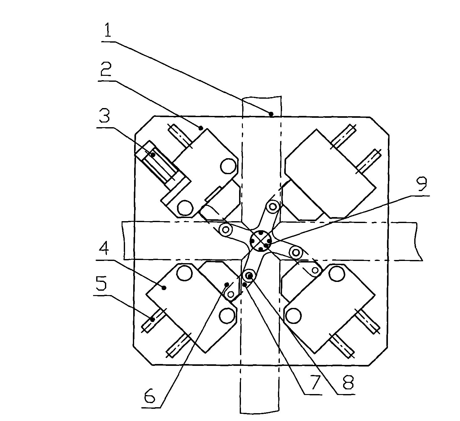
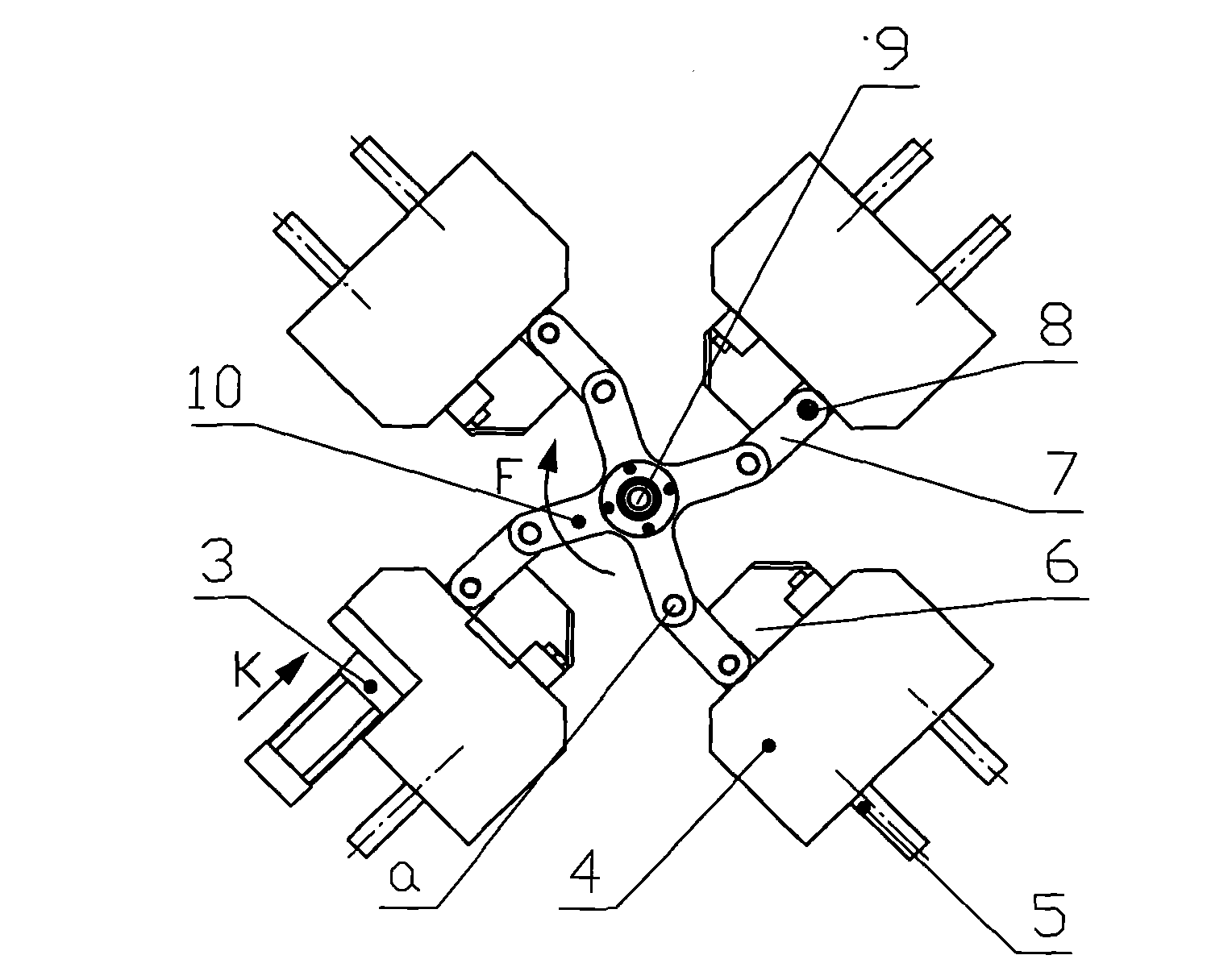
[0019] Such as figure 1 , 2 A specific embodiment of the application of the present invention in the positioning of cross-shaped workpieces is shown, which includes four slider linkages arranged on the same worktable 2, a fixed shaft 9 and a 4 A rotating plate 10 with a mounting hole a, wherein a drive mechanism is connected to the end of the slider 6 of a slider link mechanism, and the slider link mechanism is distributed along the angle bisector of the corner of the workpiece. In the slider link mechanism The slider is slidably installed on two parallel guide shafts 5 arranged at a certain distance on the workbench 2 through the guide shaft seat 4. One end of the connecting rod 7 is hinged on the slider 6 for alignment thro...


PUM


Abstract

The invention discloses a synchronous centering and positioning device which comprises more than three sliding-block connecting rod mechanisms arranged on the same workbench, a fixed shaft and a rotating plate which is provided with mounting holes that are same as the sliding-block connecting rod mechanisms quantitively according to equal division, wherein the tail end of a sliding block of one sliding-block connecting rod mechanism is connected with a driving mechanism, the sliding-block connecting rod mechanisms are all distributed along the angular bisectors of angles of a workpiece, one end of a connecting rod is hinged on a sliding block used for positioning, and the other end of the connecting rod is hinged in the mounting hole of the rotating plate; and the rotating plate is rotatably connected to the fixed shaft. The invention has the advantages: only one driving mechanism is arranged to push the sliding block connecting rod mechanisms to move so as to drive other sliding blocks to move towards the central line of the fixed shaft, thereby driving the workpiece to automatically and forcefully center and position, effectively eliminating the defect that a plurality of power sources are not synchronous due to the power and the speed and accurately and reliably positioning.

Description

(1) Technical field [0001] The invention relates to a synchronous centering and positioning device, which is used for centering and positioning the corners of polygonal workpieces with the same size and width and whose center lines intersect at the same point. (2) Background technology [0002] With the promotion and development of industrial technology, more and more processing equipment needs to perform accurate automatic centering and positioning for the same polygonal workpiece. The traditional positioning method is used on the angle bisector of each adjacent frame, respectively A set of positioning devices is arranged. Due to the difference in speed and force of the driving parts of each set of positioning devices, it is difficult to fix the same workpiece at the same position in multiple positionings, resulting in inaccurate repeated positioning, so it is brought to the processing of the workpiece. Considerable difficulty causes the unreliable processing quality of the...

Claims


Application Information

Patent Timeline
Patent Type & Authority Applications(China)
IPC IPC(8): B25B11/00B23Q3/18
Inventor 江玉超
Owner JINAN DECA MASCH CO LTD
Why Eureka
Eureka Blog
Learn More