Construction technology for stretching notch by cast-in-situ prestress box beam

A construction process and prestressing technology, applied in the direction of bridges, bridge construction, erection/assembly of bridges, etc., can solve the problems of lack of reserved structural steel bars, influence of construction period, improper construction method of blocking, etc., and it is easy to guarantee and improve the pouring quality. The effect of installation accuracy and method is simple and easy

Inactive Publication Date: 2013-01-23
CHINA CONSTR THIRD ENG BUREAU GRP CO LTD
View PDF0 Cites 0 Cited by
  • Summary
  • Abstract
  • Description
  • Claims
  • Application Information

AI Technical Summary

Problems solved by technology

), resulting in deviations in the installation of anchors, leaving hidden dangers to the quality of the project;
[0004] 2. In order to facilitate the support of the notch formwork at the notch of some projects, some steel bars of the transverse beam are cut off, and no structural steel bars are reserved in the later stage, resulting in planting or digging out bars afterwards, which not only wastes a lot of manpower , material resources, and the construction period is affected, the quality of steel connection cannot be guaranteed;
[0005] 3. The construction method of notch plugging in some projects is improper (for example: inclined mold method: as attached to the manual figure 2 ; Mortar filling method: Use high-grade mortar to fill the notch in stages until it is straight with the surrounding box girder concrete
To sum up, the construction of the lower slot of the fish-belly box girder has high technical and quality requirements, and has certain technical and construction difficulties

Method used


Image

  • Construction technology for stretching notch by cast-in-situ prestress box beam
  • Construction technology for stretching notch by cast-in-situ prestress box beam
  • Construction technology for stretching notch by cast-in-situ prestress box beam

Examples


Embodiment

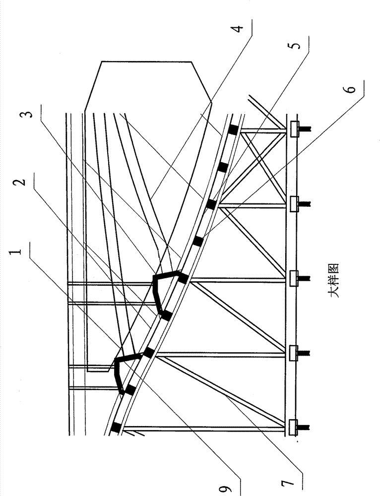
[0033] Example: see Figure 3-Figure 6

[0034] A construction process for the tension notch of a cast-in-place prestressed box girder, including the following four parts

[0035] The first step: notch formwork support

[0036] While bundling the steel bars of the box girder, fix the supporting frame of the notch formwork to the bottom form of the box girder, install the notch formwork on its supporting frame, install the fixed anchors on the notch formwork, and then carry out Installation of prestressed bellows and prestressed steel bars;

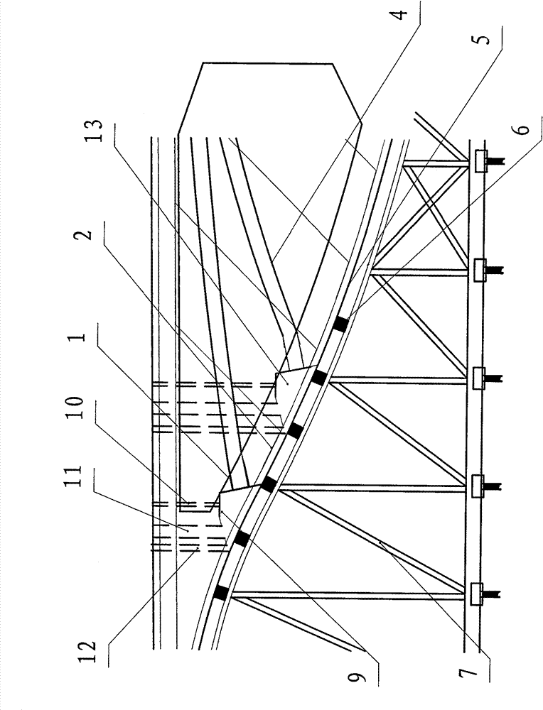
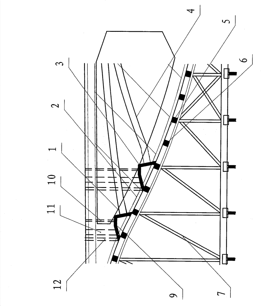
[0037] Step 2: Reserve holes for tensioning equipment suspension, secondary irrigation holes and vent holes

[0038] Use PVC pipes to reserve holes for tensioning equipment suspension, secondary pouring holes, and vent holes between the lower notch and the top surface of the box girder. The PVC pipes should avoid prestressed corrugated pipes. The vent holes mentioned At the highest point of the notch formwork; then concrete pouring of ...


PUM


Abstract

The invention discloses a construction technology for stretching a notch by a cast-in-situ prestress box beam, comprising four steps: the first step: arranging a notch die plate, positioning and fixing an anchorage by utilizing the notch die plate so as to control the inclination angle of anchorage installation and the position of the anchorage centerline, thereby improving installation accuracy;the second step: reserving a tensioning apparatus suspension hole, a secondary casting hole and an air vent to solve the problem of the construction difficulties such as recovery of intercepted steelbars of the notch, prestress stretching, secondary casting and the like; the third step: stretching prestress; and the fourth step: plugging the notch; adopting the method that a grouting material ispoured from the secondary casting hole reserved on the top part of the lower notch to replace the conventional method that inclined die casting is adopted and redundant concrete is eliminated after die removing, thereby solving the problems of the compactness and strength of the secondary casting and the tight connection between the secondary casting and an original structure, therefore, the method is simpler and easier, and the casting quality can be guaranteed more easily.

Description

technical field [0001] The invention relates to a bridge construction technology, in particular to a construction technology of a cast-in-place prestressed box girder tensioning slot. Background technique [0002] With the rapid development of science and technology, municipal bridges and other structures have become more beautiful in shape, but at the same time, some small problems in engineering construction continue to appear, and the construction of the lower notch of cast-in-place prestressed box girder is one of many problems. [0003] 1. In some projects, due to the improper support method of the notch formwork (the formwork set up to form the tension notch) (for example, the manual attached figure 1 : Directly fix the anchors on the steel skeleton of the transverse beam, and then use foam to make the anchors into the shape of tension notches; or fix the anchors on the simple formwork without reinforcement skeleton. These conditions are prone to deformation during co...

Claims


Application Information

Patent Timeline
Patent Type & Authority Patents(China)
IPC IPC(8): E01D21/00E04G21/12
Inventor 刘宏林王辉戴晓松黄刚杜雄伟李洪松程鹏马重刚张磊李琦
Owner CHINA CONSTR THIRD ENG BUREAU GRP CO LTD
Why Eureka
Try Eureka