Swimming pool bottom hydro power pushed automatic cleaner

An automatic cleaning machine and hydraulic drive technology, which is applied in swimming pools, public buildings, gymnasiums, etc., can solve the problems of insufficient use of the performance characteristics of cleaning machine components, complex structure of cleaning machines, and difficulty in cleaning machine coverage, etc. The effect of heat dissipation, simple structure and streamlined structure

Active Publication Date: 2010-03-10
TIANJIN WANGYUAN ENVIRONMENTAL PROTECTION & TECH CO LTD
View PDF0 Cites 21 Cited by
  • Summary
  • Abstract
  • Description
  • Claims
  • Application Information

AI Technical Summary

Problems solved by technology

These cleaning machines are still relatively complex in structure, and the performance characteristics of the main components of the cleaning machine have not been fully utilized
The basic way of moving the existing cleaning machine is the switchback type, so it is a difficult problem for the cleaning machine to ensure that its walking path covers the entire pool bottom
The existing pool bottom cleaning machines basically have no turning function, and the maneuverability is poor. If you want to effectively clean the bottom of the swimming pool, you must make the cleaning machine have a turning and maneuvering function, so that you can walk according to the designed cleaning path and complete the full coverage cleaning.

Method used


Image

  • Swimming pool bottom hydro power pushed automatic cleaner
  • Swimming pool bottom hydro power pushed automatic cleaner
  • Swimming pool bottom hydro power pushed automatic cleaner

Examples


Embodiment 1

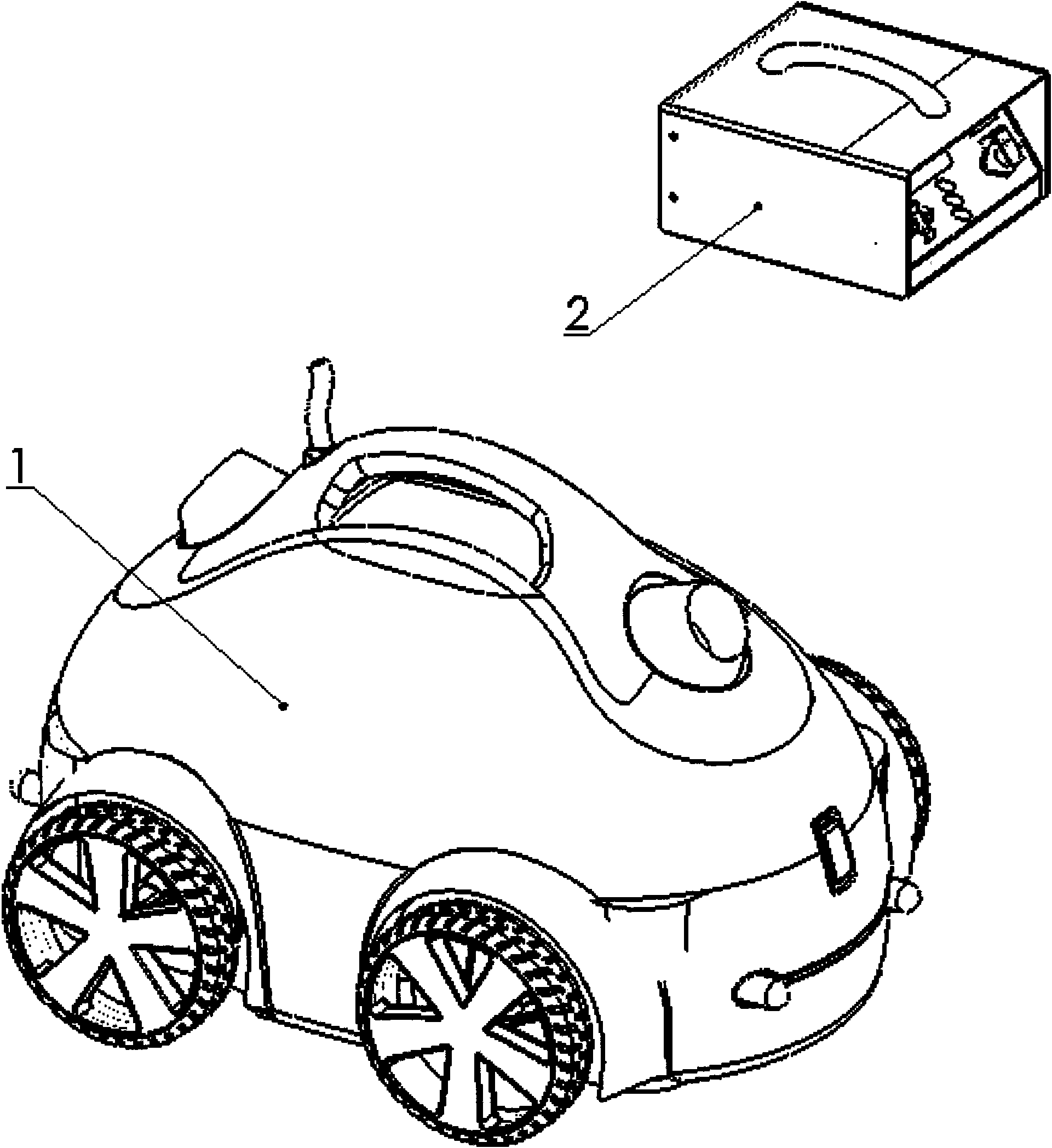
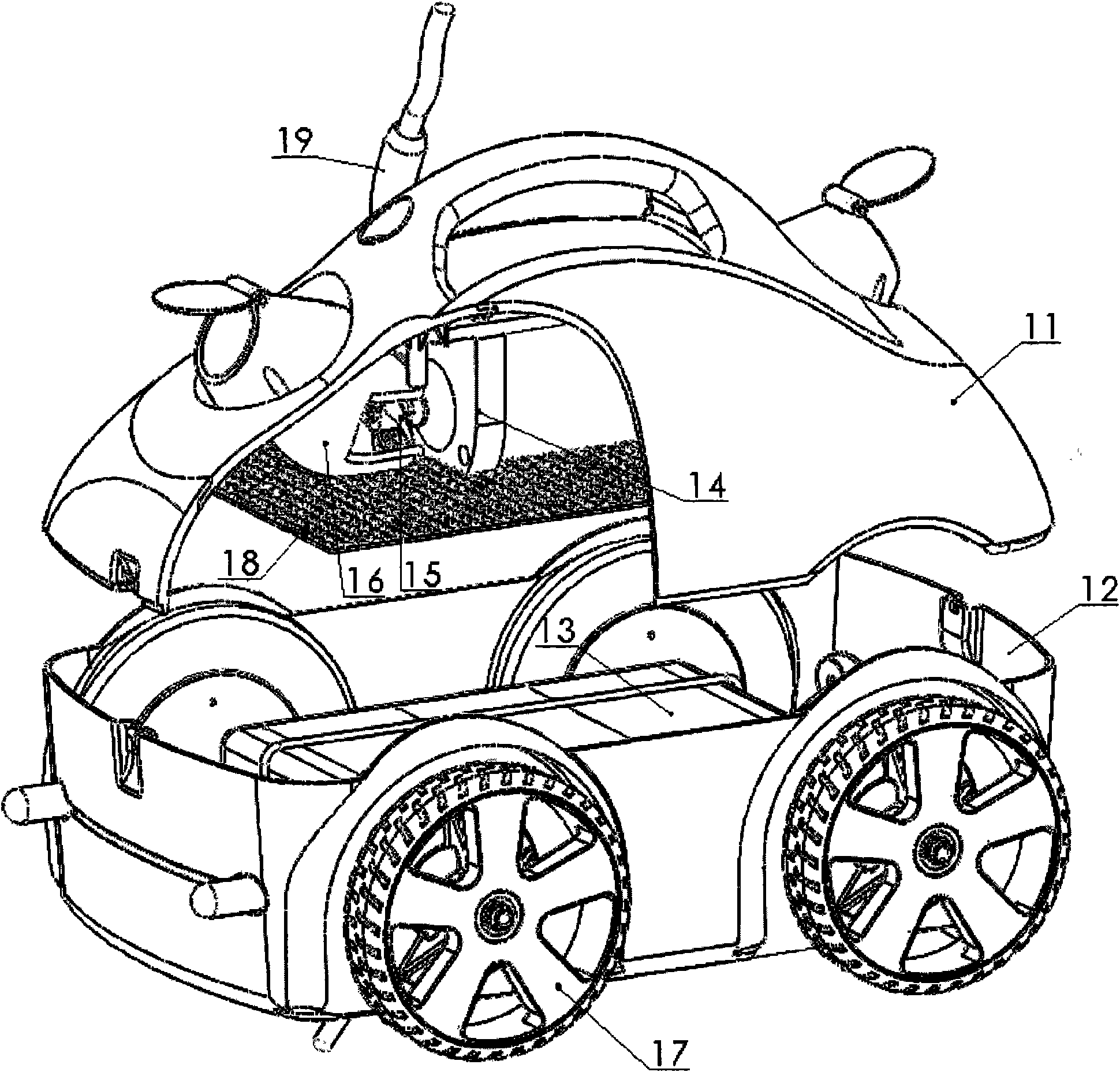
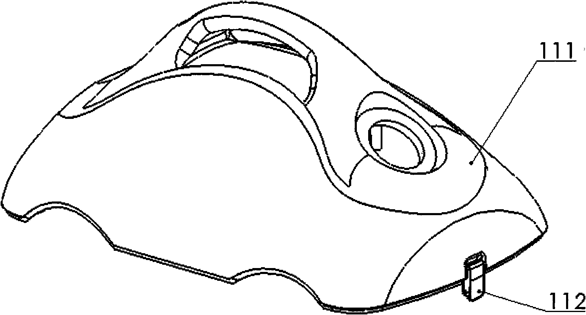
[0042] Such as figure 1 , figure 2 As shown, the hydraulically propelled automatic cleaning machine at the bottom of the swimming pool includes an underwater cleaning machine 1 and a control power supply 2; The assembly 14 is composed of a hydraulically driven jaw clutch impeller combination 15, water inlet and outlet channels 16, wheels and brackets 17, an isolation cover 18, and a buoyant cable 19; the casing cover part 11 includes a casing cover 111, Buckle 112. The double extension shaft motor assembly 14 and the inlet and outlet water channel 16 are installed on the inside top of the casing cover 111, and the center line of the front and back inlet and outlet water flow channel 16 is coaxial with the double extension shaft motor assembly 14; the lock catch 112 is the casing cover 111 and The connecting lock piece of the machine casing 121 is sealed; the casing part 12 includes a casing 121, a one-way water inlet valve 122, a suction pipe 123, a one-way drain valve 124,...

Embodiment 2

[0046] Such as Figure 11-14 As shown, a hydraulically propelled automatic cleaning machine for the bottom of a pool with a turning function includes an underwater cleaning machine A with a turning function, a control power supply B and a remote control C. The underwater cleaning machine A with turning function is based on the technical solution of an underwater cleaning machine 1 in the embodiment, and adopts two or more double-extending shaft motor assemblies 14 arranged in parallel horizontally, and the corresponding water inlet and outlet channels 16 and the impeller 15 with a hydraulically driven jaw clutch form two or more axial flow pump sets A4 arranged in parallel horizontally. When the impellers 151 at the same end in the axial flow pump set A4 work at the same time, they have the function of turning and cleaning underwater The machine walks in a straight line; when only one impeller 151 is working or the impellers 151 at both ends of the axial flow pump group A4 are...


PUM


Abstract

The invention relates to a swimming pool bottom hydro power pushed automatic cleaner, comprising an underwater cleaner and a control power supply which are connected by a buoyancy cable; wherein the underwater cleaner comprises a shell cover part, a shell body part, a filter, a double extension motor assembly, a hydro power driven jaw clutch pulley assembly, a water flow channel, a wheel and support, an isolated hood and a cable with a buoy. Along with the rotating direction of the motor, the hydro power driven jaw clutch pulley assembly is reliably meshed or separated under the action of hydro power; the pulley changes working condition, so as to realize jet water to be flowed out and further change travel direction of the cleaner; the shell touches wall to cause the cleaner to automatically adjust direction after touching the wall, so as to change travel route after touching the wall; and an arranged suction tube and a unidirectional drainage valve avoid eddy diffusion of travel of the cleaner on sewage at the bottom and reduce the weight of the cleaner when being taken out from water. In addition, two or multiple axial-flow pumps are arranged horizontally, so that the cleaner has turning function and ordered full cover washing is realized.

Description

technical field [0001] The invention relates to a swimming pool cleaning device, in particular to an automatic cleaning machine for cleaning the bottom of a swimming pool. Background technique [0002] The cleanliness of the swimming pool is very important, it is very important to the health of swimmers, therefore, the swimming pool should be cleaned frequently to remove the deposited dirt on the bottom of the pool, prevent the growth of bacteria and algae, and ensure the cleanliness of the pool water and the sanitation of the pool. [0003] Usually, the method for cleaning the bottom of the swimming pool is to use a suction cup device to suck the bottom of the pool. In the prior art, a more fashionable method is to use a cleaning machine that can automatically move at the bottom of the swimming pool to clean the bottom of the pool. This kind of cleaning machine has a water pump in its shell. The pool water containing dirt at the bottom of the pool passes through the one-wa...

Claims


Application Information

Patent Timeline
Patent Type & Authority Applications(China)
IPC IPC(8): E04H4/16
CPCE04H4/1654
Inventor 付桂兰余浅邹常胜刘建王必昌宫欣茹吕晓洲岑璞
Owner TIANJIN WANGYUAN ENVIRONMENTAL PROTECTION & TECH CO LTD
Why Eureka
Try Eureka