Stationary remote control transmitter

A transmitter, fixed technology, used in telemetry/remote control selection device, image communication, signal transmission system, etc., can solve problems such as difficulty in fine adjustment of slats, incoordination, time lag, etc.

Inactive Publication Date: 2010-03-10
SMK CO LTD
View PDF2 Cites 1 Cited by
  • Summary
  • Abstract
  • Description
  • Claims
  • Application Information

AI Technical Summary

Problems solved by technology

Therefore, since the jog dial is separated from the display unit, the direction of rotation of the jog dial for desired control cannot be guided by the display on the display unit, and it is impossible to convey to the operator which direction to turn the jog dial. well-behaved problem
[0009] Moreover, when controlling the rotational movement of the controlled device according to the rotation operation of the jog dial, depending on the relative position of the remote control device and the controlled device, the rotational direction of the controlled device may be different from the rotation of the jog dial. The operation direction is reversed, the operator mistakenly rotates the direction of the jog dial, or performs the rotation operation with an uncoordinated feeling
[0010] In addition, the remote transmitter of Patent Document 2 displays the rotational posture of the controlled device controlled by the rotational motion on the input switch, and guides the direction of the rotational motion of the controlled device based on the input operation to the input switch. The pressing direction of the operated switch has nothing to do with the rotational posture and direction of the rotational movement of the controlled device, and it is also an input operation with a sense of incongruity.
[0011] In addition, the slats are controlled by the rotation of the slat angle adjustment motor during the input operation of the input switch, but since there is a time lag between the input operation of the input switch and the rotation of the slats, the slats are It is extremely difficult to fine-tune the posture of the bar

Method used


Image

  • Stationary remote control transmitter
  • Stationary remote control transmitter
  • Stationary remote control transmitter

Examples


Embodiment Construction

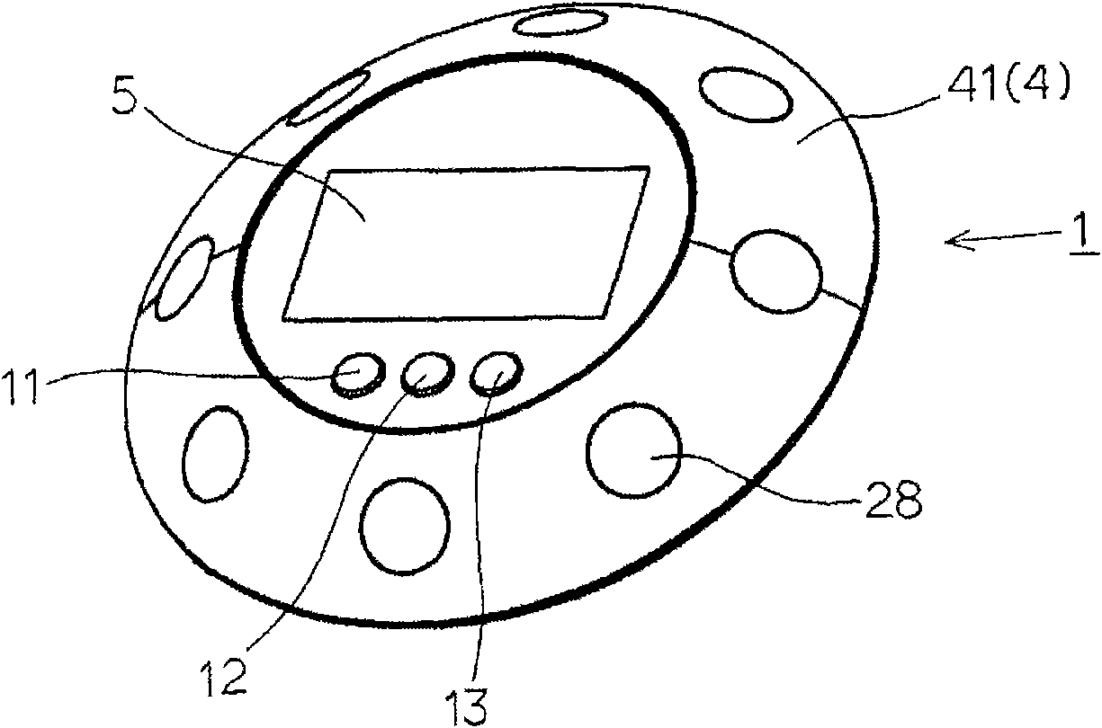
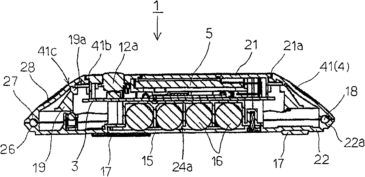
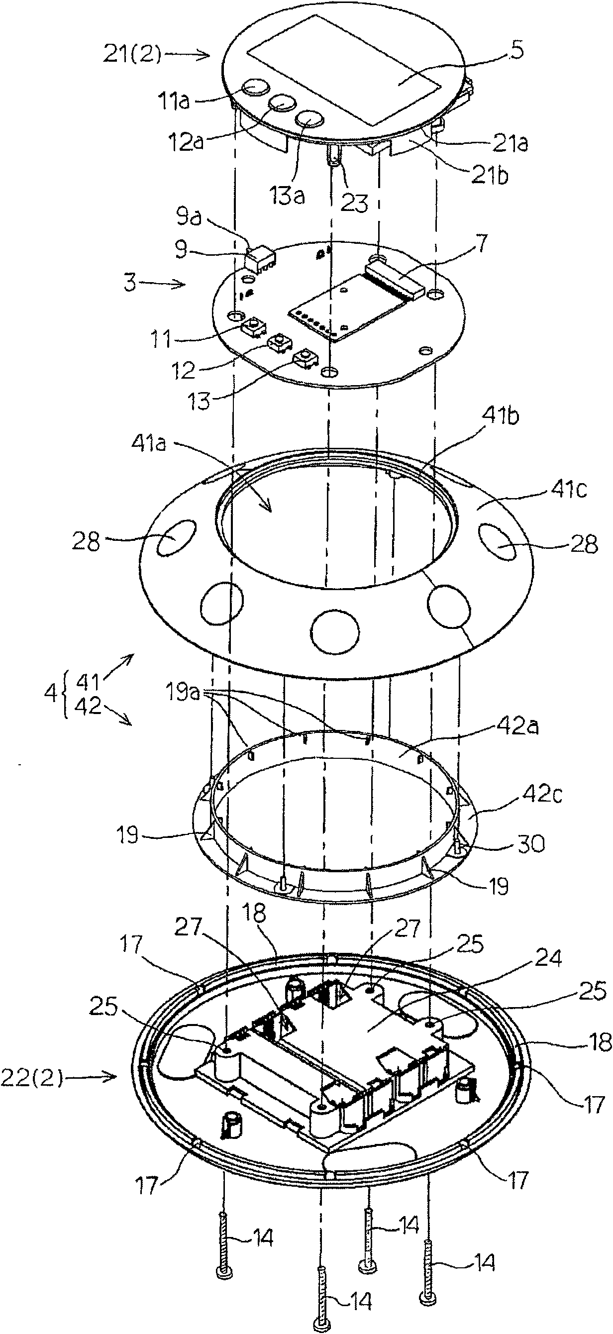
[0054] Below, use Figure 1 to Figure 9 , the stationary remote control transmitter 1 according to one embodiment of the present invention will be described. figure 1 It is a perspective view of a fixed remote control transmitter 1, figure 2 is its longitudinal section view, image 3 It is an exploded perspective view viewed from above of the fixed remote control transmitter 1, Figure 4 It is an exploded perspective view of the fixed remote control transmitter 1 seen from below.

[0055] Such as image 3 , Figure 4 As shown, the fixed remote control transmitter 1 has: an insulating housing 2 composed of a small-diameter disc part 21 and a large-diameter disc part 22; A circular printed circuit board 3 for mounting; an annular operating portion 4 composed of an annular jog dial 41 and an operating ring 42; Input switches 11 , 12 , 13 and liquid crystal display element 5 .

[0056] The small-diameter disc portion 21 is formed into a disc shape with synthetic resin, and...


PUM


Abstract

In a controlling mode wherein control content for rotational operation control of a controlled device has been selected through an inputting operation of an inputting switch (11, 12, 13), a displayingunit (5) that is provided on a surface of a case (2) that is displayed on the rotational center axis side of an operating unit (4) displays the rotational operation directions for rotational operation control, to perform rotational operation control of a controlled device in a rotational operation direction displayed on the displaying unit (5) by a rotational operation of an operating unit (4) ina direction that matches the rotational operation direction that is displayed on the displaying unit (5).

Description

technical field [0001] The present invention relates to a fixed type remote control transmitter for controlling transmission of control data from a controlled device, and more specifically, to a fixed type remote control transmitter provided with an operating portion for rotation operation. Background technique [0002] Conventionally, as a remote control transmitter for remote control of video reproduction equipment such as a DVD recorder, a ring-shaped dial key called a jog dial is rotatably attached to a casing. , and according to the rotation operation of the jog dial, a remote control transmitter that performs continuous movement playback or variable speed playback control on video recorded in a DVD recorder (Patent Document 1). [0003] In this kind of remote control transmitter, control contents (for example, power ON, OFF, fast forward, rewind, playback, etc.) After the determination key on the casing rotates any control content, for example, select "Reproduction", ...

Claims


Application Information

Patent Timeline
Patent Type & Authority Applications(China)
IPC IPC(8): H04Q9/00G08C17/02H04N5/00
CPCH01H2025/045H01H9/0235G08C17/02
Inventor 大塚健二
Owner SMK CO LTD
Why Eureka
Try Eureka