Fusion device, systems and methods thereof

Inactive Publication Date: 2011-01-06
PIONEER SURGICAL TECH INC
View PDF2 Cites 82 Cited by
  • Summary
  • Abstract
  • Description
  • Claims
  • Application Information

AI Technical Summary

Benefits of technology

[0016]The spinal fusion device of the invention is implanted within an intervertebral space between adjacent upper and lower vertebrae and secured to the vertebrae with cement. The fusion device comprises a body having upper and lower endplate facing surfaces for contacting adjacent vertebrae, with one or more sidewalls formed therebetween. The fusion device includes upper and lower endplate facing surfaces each having at least one opening for delivering cement material to adjacent contact surfaces of the vertebrae above and below the implant. Utilizing quick-setting cement compositions with the device can allow for almost immediate fusion of the vertebrae, thus, reducing or eliminating the need for adjuvant fixation

Problems solved by technology

A variety of spinal conditions result in a person experiencing pain or limited physical activity and ability.
Some of these conditions can be life-threatening, while others cause impingement on the spinal cord resulting in pain and a lack of mobility.
However, the absence of proper medical care may lead to further damage and degeneration of spinal health and to permanent spinal cord damage.
Damage to the spine often results in reduced physiological capability.
In more severe cases, the damage may allow the nucleus to leak from the annulus.
In any event, such damage often causes the vertebrae to shift closer or compress, and often causes a portion of the disc to press against the spinal

Method used


Image

  • Fusion device, systems and methods thereof
  • Fusion device, systems and methods thereof
  • Fusion device, systems and methods thereof

Examples


Example

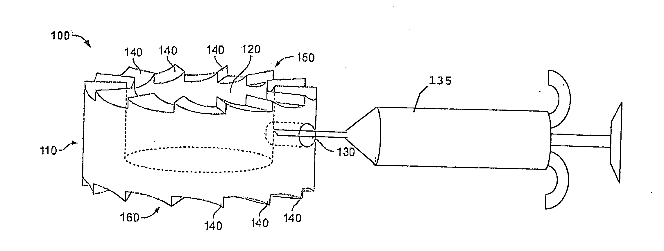
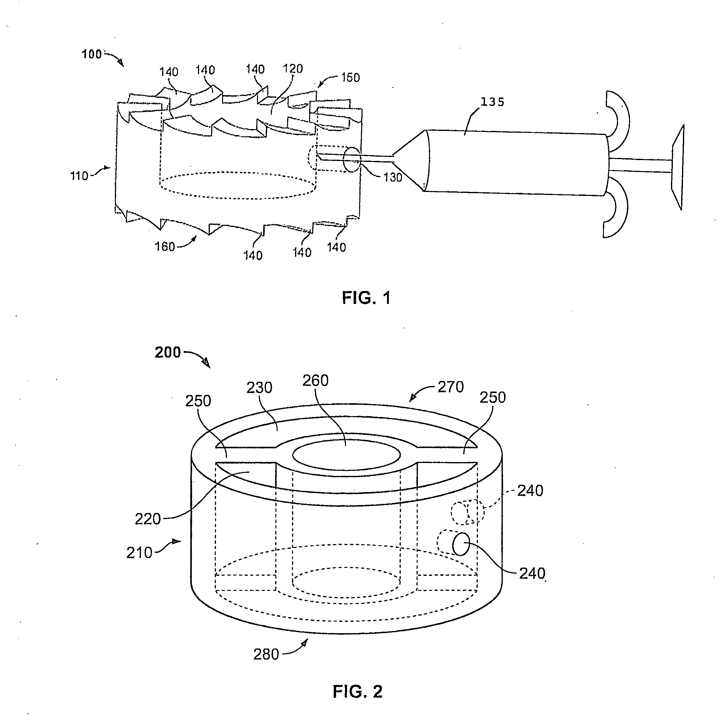
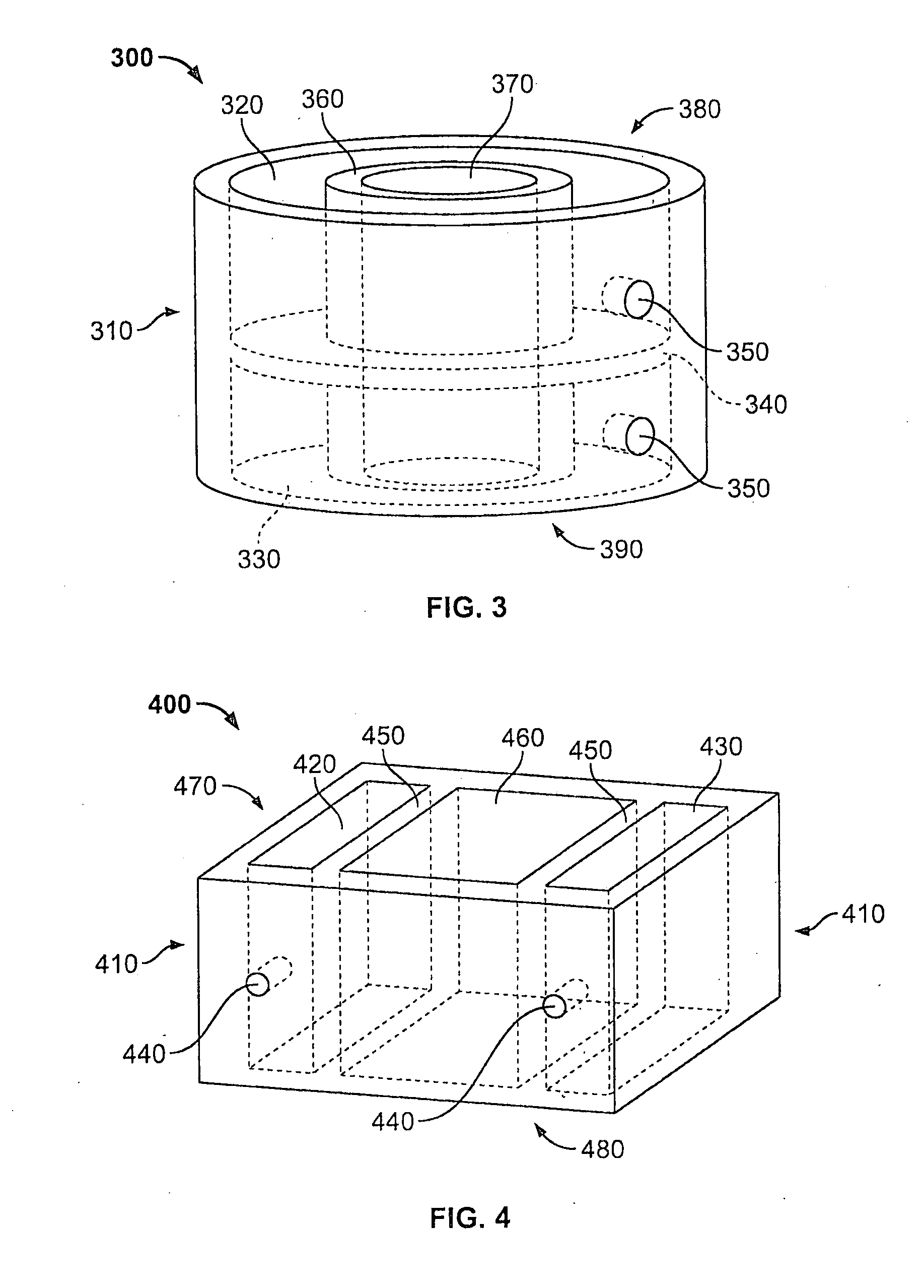
[0038]The spinal fusion device of the invention is used to maintain disc height between two adjacent vertebral bodies while bone forms between the two vertebrae. The device permits injection of cement into one or more hollow cores in the fusion device. The cement fills the one or more hollow cores and engages the vertebral body surfaces located on one or both sides of the implanted device. Once the cement has set, independent motion of the vertebrae is substantially or wholly eliminated. The device, systems and methods of the invention provide for reduced time for fixation and improved stability of the vertebral motion segment, thereby reducing or eliminating the need for adjuvant fixation. By reducing or eliminating the drilling, tapping or insertion of screws associated with adjuvant fixation, the invention provides for shorter spinal fusion procedures. In some embodiments, as boney spinal fusion occurs, the cement will resorb and act as a continuous scaffold for tissue ingrowth w...


PUM

PropertyMeasurementUnit
Angleaaaaaaaaaa
Pressureaaaaaaaaaa
Flow rateaaaaaaaaaa

Abstract

The spinal fusion device (100) of the invention is implanted within an intervertebral space between adjacent upper and lower vertebrae and secured to the vertebrae with cement. The fusion device includes upper and lower endplate facing surfaces (150, 160) each having at least one opening (120) for delivering cement material to adjacent contact surfaces of the vertebrae above and below the implant. Utilizing quick-setting cement compositions with the device <:an allow for almost immediate fusion of the vertebrae, thus, reducing or eliminating the need for adjuvant fixation devices such as screws, plates, and/or rods, while also simultaneously providing precise delivery of cement to contact surfaces between the fusion device and vertebrae.

Description

CROSS REFERENCE TO RELATED APPLICATIONS[0001]This application claims the benefit of the filing date of U.S. Provisional Application No. 60 / 851,972, filed on Oct. 16, 2006, which is hereby incorporated by reference herein in its entirety.FIELD OF THE INVENTION[0002]The invention relates to spinal fusion implant devices for fusing adjacent vertebrae and, in particular, to implant devices positionable in the intervertebral space and fixed in place using a cement composition.BACKGROUND OF INVENTION[0003]The spine principally includes a series of vertebrae and spinal discs located in a space between adjacent vertebrae. The vertebrae are formed of hard bone while the discs comprise a comparatively soft annulus and nucleus. The discs support the vertebrae in proper position and enable the torso to be rotated and to bend laterally and anteriorly-posteriorly. The discs also act as shock absorbers or cushions when the spine is experiencing shock, such as during running or jumping.[0004]A vari...

Claims


Application Information

Patent Timeline
IPC IPC(8): A61F2/44
CPCA61B17/7098A61F2310/00353A61F2/441A61F2/4455A61F2/4465A61F2/447A61F2002/2817A61F2002/2835A61F2002/30062A61F2002/302A61F2002/30225A61F2002/30579A61F2002/30583A61F2002/30586A61F2002/30772A61F2002/30904A61F2002/4495A61F2002/4631A61F2210/0004A61F2210/0085A61F2230/0065A61F2230/0069A61F2310/00011A61F2310/00179A61F2310/00293A61F2/28
Inventor AHN, EDWARD S.CVINAR, JOHN
Owner PIONEER SURGICAL TECH INC
Why Eureka
Try Eureka