Panoramic x-ray apparatus and positioning of a layer to be imaged for panoramic imaging

A panoramic and equipment technology, which is applied in the fields of radiodiagnostic instruments, radiodiagnostic clinical applications, patient positioning for diagnosis, etc. It can solve the problems of difficult and slow execution of the imaging process, complex imaging equipment, etc.

Active Publication Date: 2010-03-10
PLANMECA
View PDF0 Cites 13 Cited by
  • Summary
  • Abstract
  • Description
  • Claims
  • Application Information

AI Technical Summary

Problems solved by technology

Further, these types of solutions may also require the integration of various accessories into the imaging device and possibly other specific arrangements which further complicate the imaging device and may even make the imaging process difficult or slow to perform

Method used


Image

  • Panoramic x-ray apparatus and positioning of a layer to be imaged for panoramic imaging
  • Panoramic x-ray apparatus and positioning of a layer to be imaged for panoramic imaging
  • Panoramic x-ray apparatus and positioning of a layer to be imaged for panoramic imaging

Examples


Embodiment Construction

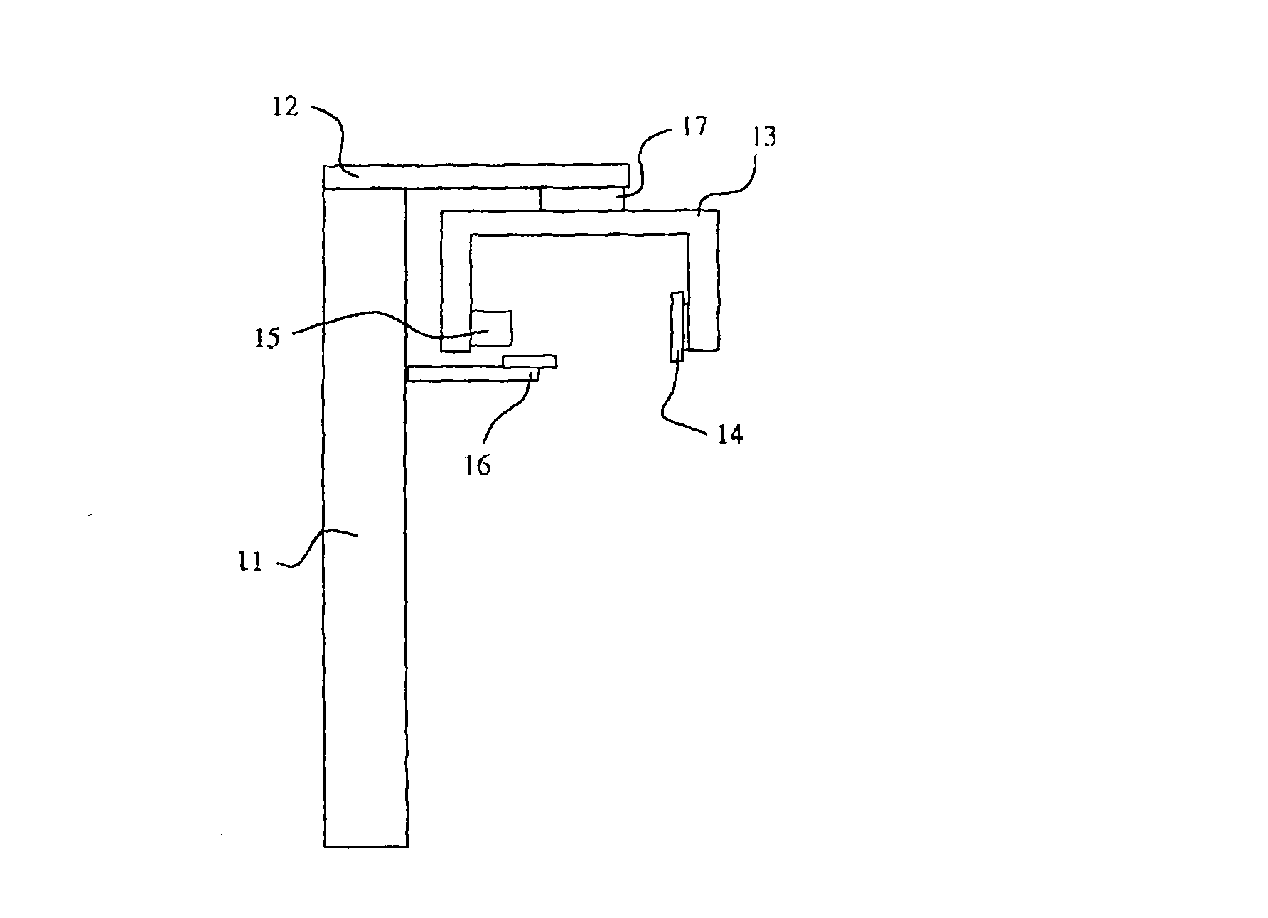
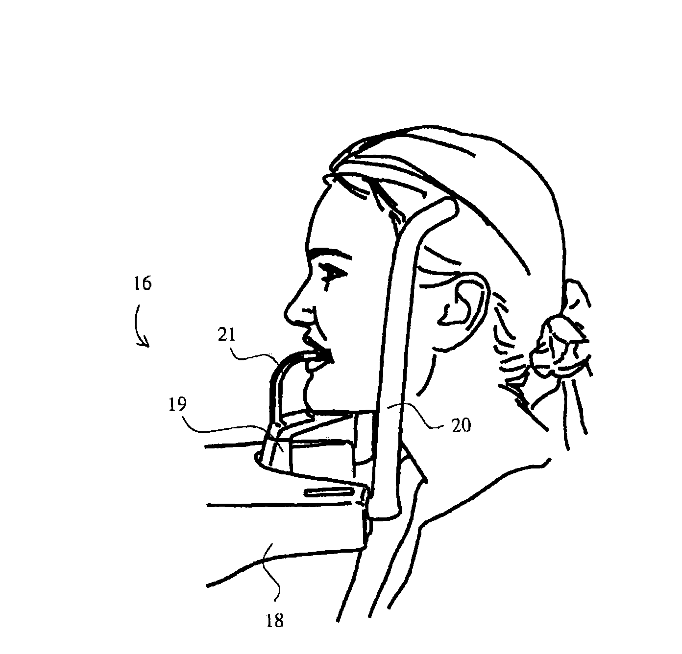
[0020] figure 1 The basic configuration of a typical panoramic x-ray facility is shown. according to figure 1 The device comprises a cylindrical body part (11) and a horizontal support arm (12) attached to the body part. Substantially at the other end of the support arm (12), there is arranged an imaging arm (13), called a C-arm, which supports an image information receiver (14) and a radiation source (15). Further, a patient support device (16) is arranged to the main body part (11).

[0021] The imaging arm (13) is arranged to rotate relative to the support arm (12). Additionally, an apparatus configuration suitable for use with the present invention must allow the imaging arm (13) to be positioned in such a way that the imaging device can be positioned for taking side profile images of an anatomical structure positioned in the patient support device (16). movement on a horizontal surface. This can for example be achieved by giving the construction (17) with x,y degrees...


PUM


Abstract

The invention concerns a panoramic x-ray apparatus and a method for positioning a layer to be imaged for dental panoramic x-ray imaging. The x-ray apparatus comprises a radiation source (15) and an image information receiver (14) arranged at a distance from each other at a turnable arm part (13). In the invention, a side profile x-ray image is taken of the frontal area of a dental arch positionedto be imaged, such a vertical tomographic layer of the incisor area is determined from the side profile x-ray image in question that would be optimal in view of the layer becoming imaged sharp in panoramic x-ray imaging of the dental arch and, subsequently, the imaging means (14, 15) are driven during the panoramic exposure in such a way that the layer chosen from the side profile x-ray image becomes imaged sharp in the panoramic x-ray image.

Description

technical field [0001] The invention relates to a panoramic x-ray device according to patent claim 1 and a method according to claim 7 for positioning a layer to be imaged for panoramic x-ray imaging. Background technique [0002] Panoramic x-ray imaging is slice imaging, tomographic imaging, in which during the imaging scan the radiation source and image information receiver are exposed during exposure such that substantially the dental arch is sharply imaged while other anatomical structures of the skull become blurred in the image being formed. Get blurred in such a way that it rotates relative to the dental arch. Typically, the imaging scan and the associated rotational movement of the imaging device producing the tomographic effect is carried out in a horizontal plane, in some specific imaging modes the tomographic effect may also be produced by moving partly in a plane different from the horizontal plane. A dental panoramic x-ray image shows the dental arch as it unfo...

Claims


Application Information

Patent Timeline
Patent Type & Authority Applications(China)
IPC IPC(8): A61B6/14A61B6/04G06T7/00G06N3/02
CPCA61B6/469A61B6/488A61B6/14
Inventor C·德戈德津斯凯S·克藤恩
Owner PLANMECA
Why Eureka
Try Eureka