
Dust collecting bucket for dust catcher

A technology for dust collection barrels and vacuum cleaners, applied in the direction of suction filters, etc., can solve the problems affecting the use of vacuum cleaners and the effect of dust removal, affecting the product qualification rate, and complicated installation of dust collection barrels, so as to avoid dust leakage and simple and effective sealing , the effect of the best vacuuming effect

Inactive Publication Date: 2010-03-17
LG ELECTRONICS (TIANJIN) APPLIANCES CO LTD
View PDF0 Cites 0 Cited by
  • Summary
  • Abstract
  • Description
  • Claims
  • Application Information

AI Technical Summary

Problems solved by technology

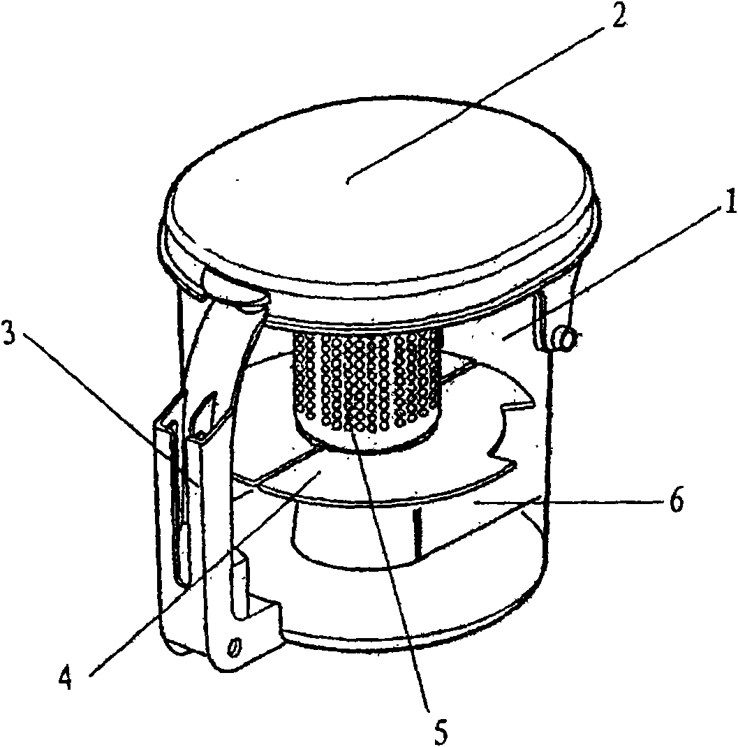
[0008] But above-mentioned vacuum cleaner dust-collecting barrel of prior art, its outward appearance structure is made up of two parts of bucket body and bucket cover, and the air inlet that is positioned at the top of bucket body is close to the junction of bucket body and bucket cover, therefore, when vacuum cleaner is running, from When the air mixed with dust entering the air inlet forms a cyclone on the upper part of the dust collecting bucket and rotates rapidly, there is a problem that the dust leaks from the gap between the bucket body and the bucket cover around the air inlet due to the large amount of air intake. Affect the use of the vacuum cleaner and the effect of removing dust
In addition, other components such as the partition plate 4 and the handle 3 in the dust collection bucket of the above-mentioned vacuum cleaner are all assembled in the dust collection bucket, so the installation of the dust collection bucket is complicated, time-consuming and laborious, and the bucket body is poorly sealed, which affects the qualification of the product. Rate

Method used


Image

  • Dust collecting bucket for dust catcher
  • Dust collecting bucket for dust catcher
  • Dust collecting bucket for dust catcher

Examples


Embodiment Construction

[0023] In order to enable those skilled in the art to better understand the solution of the present invention, the present invention will be further described in detail below in conjunction with the accompanying drawings and embodiments.

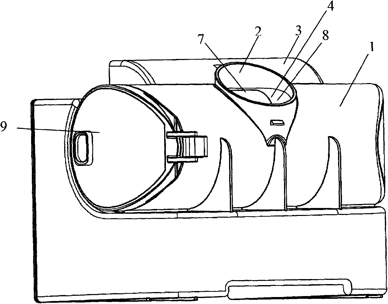
[0024] Such as figure 2 As shown, a dust collecting barrel of a vacuum cleaner provided by the present invention includes a barrel body 1, and an air inlet 2 and a handle 3 are arranged on the top of the barrel body 1. figure 2 Among them, the air inlet 2 is located directly in front of the handle 3, and the air inlet 2 is connected to the outside of the vacuum cleaner. By setting the handle 3, the dust collecting bucket of the present invention can be conveniently removed from the vacuum cleaner. loading and unloading.

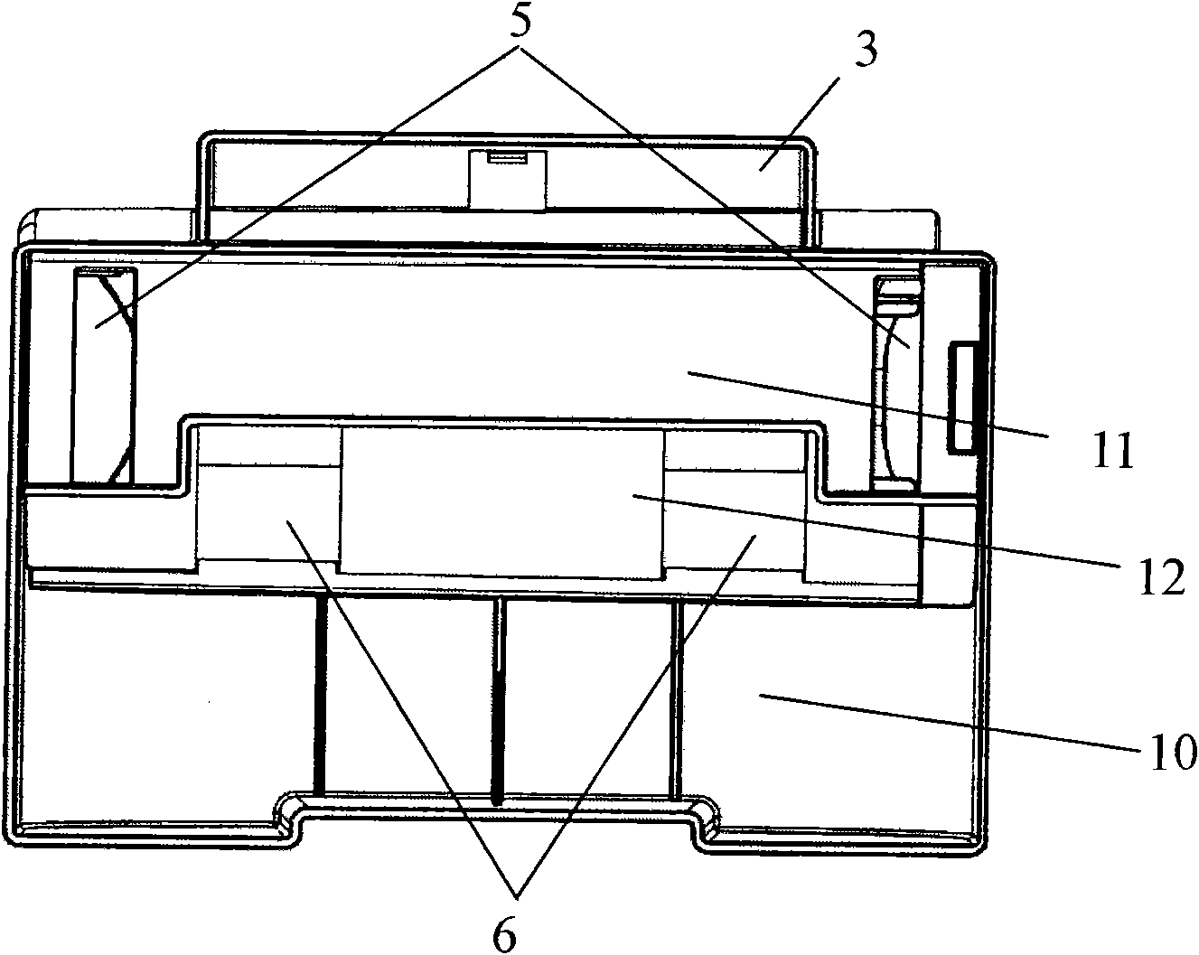
[0025] Such as figure 2 , image 3 As shown, the barrel body 1 has two chambers, a dust separation chamber 8 and a dust collection chamber 10 distributed up and down, the dust separation chamber 8 communicates with th...


PUM


Abstract

The invention discloses a dust collecting bucket for a dust catcher, which comprises a bucket body 1, wherein the bucket body 1 comprises a dust separation cavity 8 and a dust collection cavity 10; the bucket body 1 is provided with an air inlet 2; the dust separation cavity 8 is communicated with the air inlet 2; a filter (4) is arranged in the dust separation cavity 8 of the bucket body 1; and the bucket body 1 is formed integrally. The dust collecting bucket is formed integrally, so that the dust collecting bucket can be sealed simply and effectively and be prevented from leaking the dust.Furthermore, the dust collecting efficiency and the dust collecting effect of the dust collecting bucket for the dust catcher are improved, so that the dust catcher can achieve better dust collectingeffect. Moreover, the integrally-formed dust collecting bucket provided by the invention can reduce the number of moulds required for producing the dust collecting bucket so as to reduce the production cost of the dust collecting bucket.

Description

technical field [0001] The invention relates to the technical field of mechanical dust removal, in particular to a dust collecting barrel of a vacuum cleaner. Background technique [0002] Generally, a vacuum cleaner is a device that uses a vacuum to generate suction to inhale air, make the air flow through various filters, filter foreign objects in the air, and clean the room. [0003] Generally speaking, a vacuum cleaner mainly includes a suction device and a suction pipeline. The suction device mainly formed by a motor and a fan is arranged in the body. The suction pipeline includes a suction head and a suction pipe. The suction head has a downward opening. The suction port communicates with the air inlet of the fan inside the body through the telescopic pipe and the flexible pipe of the suction pipe. When the vacuum cleaner is running, the motor drives the impeller of the fan to rotate at a high speed, exhausting the air in the vacuum cleaner, forming an instantaneous v...

Claims


Application Information

Patent Timeline
IPC IPC(8): A47L9/10A47L9/12
Inventor 张庆南
Owner LG ELECTRONICS (TIANJIN) APPLIANCES CO LTD
Learn More