
Electric switch

Active Publication Date: 2018-03-22
JOHNSON ELECTRIC INTERNATIONAL AG
View PDF8 Cites 1 Cited by
  • Summary
  • Abstract
  • Description
  • Claims
  • Application Information

AI Technical Summary

Benefits of technology

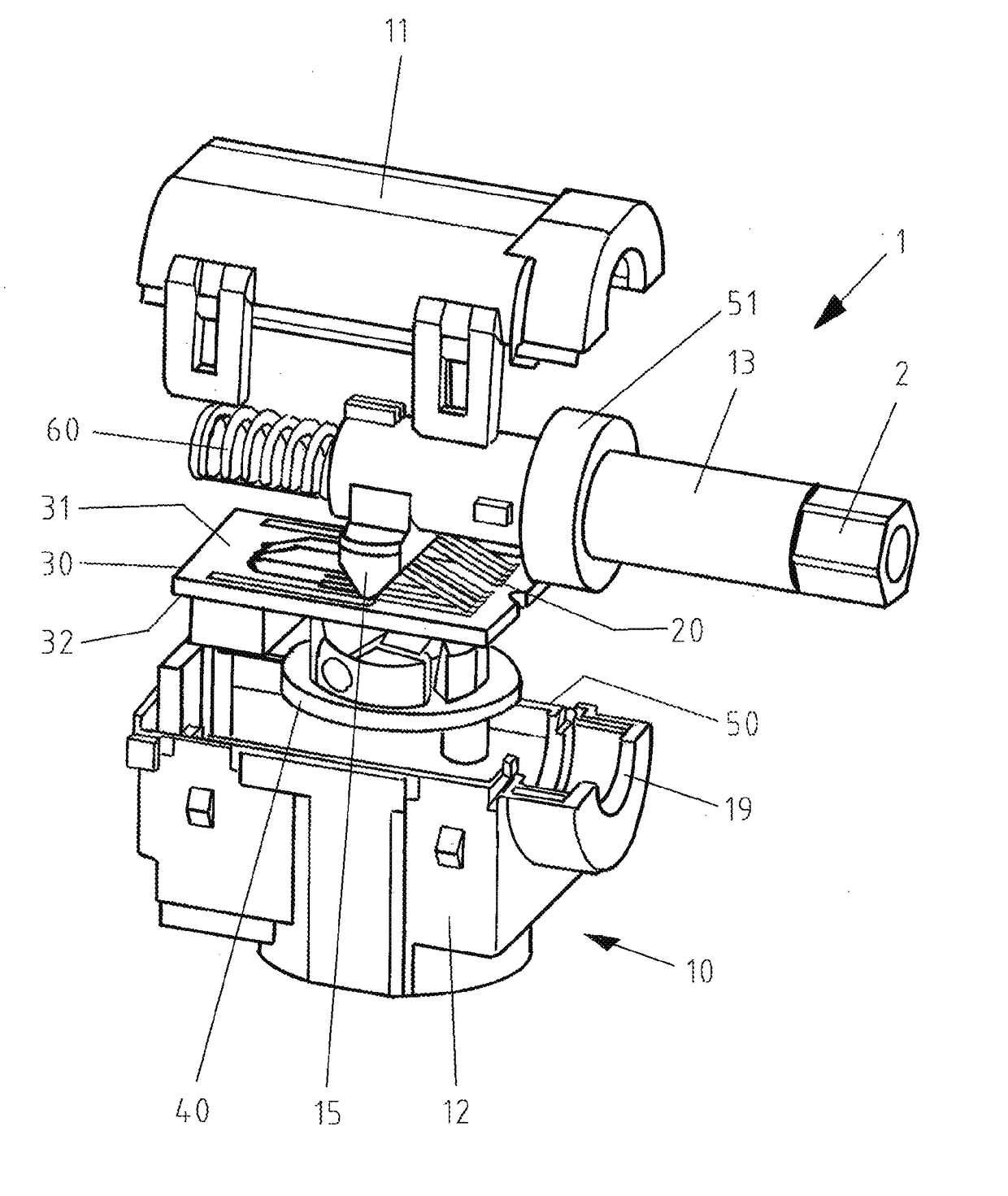
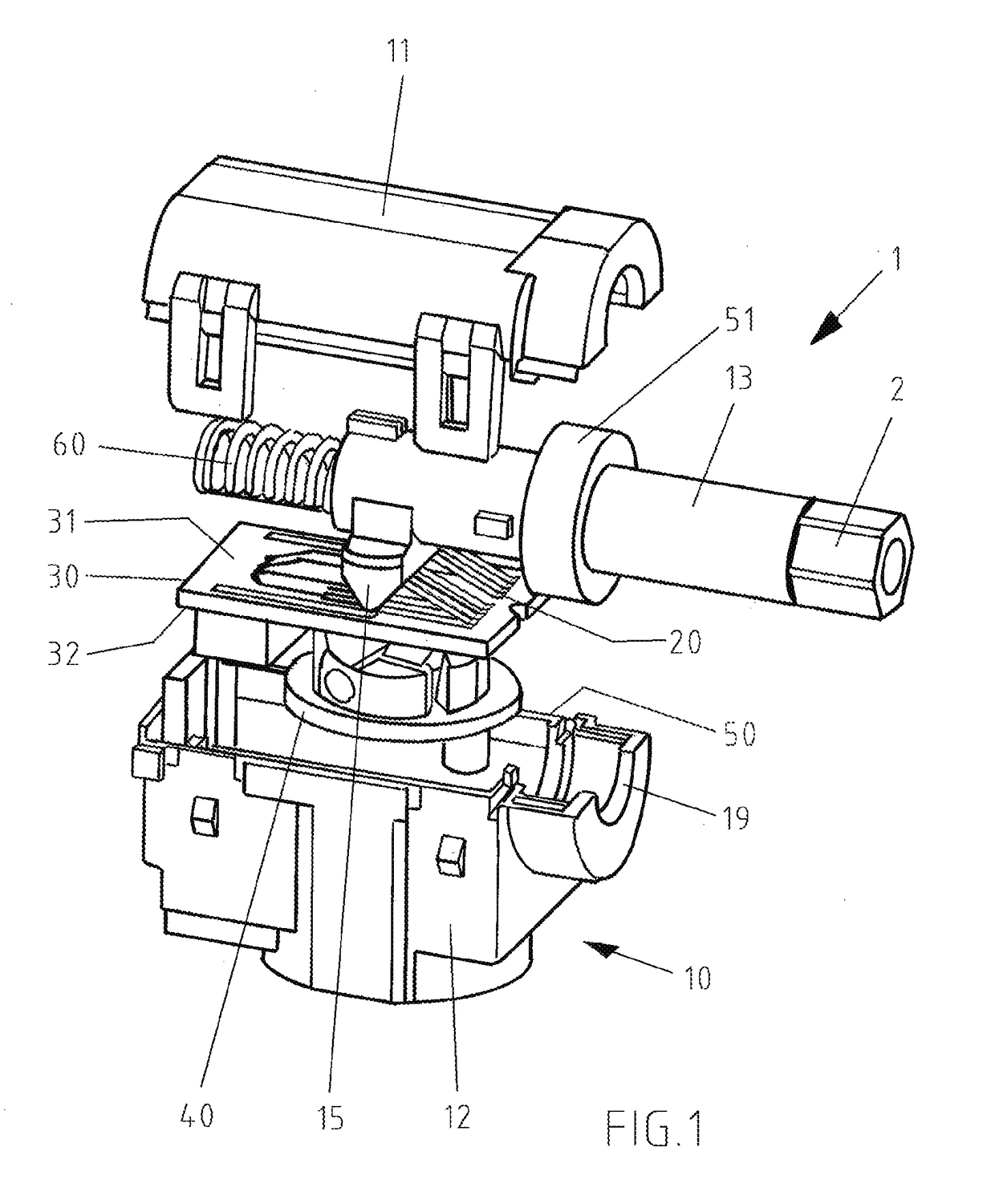
The invention is a small and compact electric switch that can be easily sealed in a housing. It has simplified contacts that eliminate the need for soldering and clamping, making assembly easier and reducing manufacturing costs. Additionally, it can be designed to be low in height.

Problems solved by technology

This requires a high number of contact systems, which leads to a complex structure of the switch.

Method used


Image

  • Electric switch
  • Electric switch
  • Electric switch

Examples


Embodiment Construction

[0018]The technical solutions of the embodiments of the present invention will be clearly and completely described as follows with reference to the accompanying drawings. Apparently, the embodiments as described below are merely part of, rather than all, embodiments of the present invention. Based on the embodiments of the present invention, any other embodiment obtained by a person skilled in the art without paying any creative effort shall fall within the protection scope of the present invention.

[0019]It is noted that, when a component is described to be “fixed” to another component, it can be directly fixed to the another component or there may be an intermediate component. When a component is described to be “connected” to another component, it can be directly connected to the another component or there may be an intermediate component. When a component is described to be “disposed” on another component, it can be directly disposed on the another component or there may be an in...


PUM


Abstract

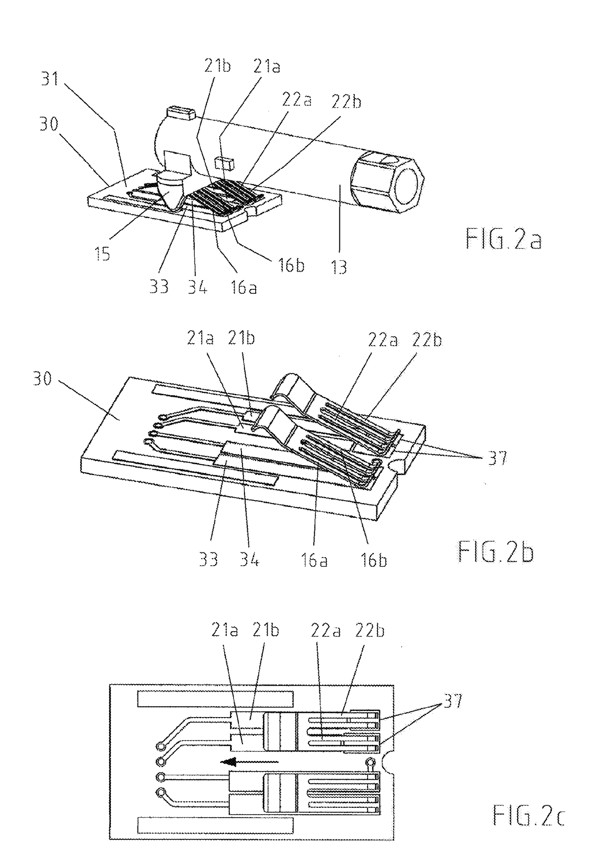
The invention relates to an electric switch for electrical devices having a circuit board immovably arranged in a switch housing said circuit board including on one of its surfaces the contact paths of a contact system as well as contact surfaces in the form of potentiometer tracks. The contact paths interact with sliding contacts of the contact system and the potentiometer tracks interact with additional sliding contacts in order to set the revolutions per minute or the torque of the electric motor, wherein movement of the plunger causes the sliding contacts of the contact system to come into contact with the associated contact paths, and, in this position of the plunger, which is the on position of the switch, the sliding contacts used for changing the direction of rotation are in the same way already in contact with the associated potentiometer tracks on the circuit board.

Description

CROSS REFERENCE TO RELATED APPLICATIONS[0001]This non-provisional patent application claims priority under 35 U.S.C. § 119(a) from Patent Application No. 10 2016 117 786.5 filed in Germany on Sep. 21, 2016.FIELD OF THE INVENTION[0002]The present invention relates to an electric switch, in particular to one used for manually operated power tools having an electric motorBACKGROUND OF THE INVENTION[0003]In general, electric switches of this type for manually operated power tools and appliances, such as electric drills, cordless screwdrivers, hammer drills or the like, include, an electric circuit which can be switched by an activation element that is activated from outside, control and regulation of the rotational speed or torque of the motor. In general, rotary or slide potentiometers are used for this purpose. The use of a mechanical changeover device in addition to this rotational speed control is also known. This requires a high number of contact systems, which leads to a complex s...

Claims


Application Information

Patent Timeline
IPC IPC(8): H01H15/10H01H15/04
CPCH01H15/10H01H15/04H01H2239/01H01H2205/002H01H2201/004H01H2223/002H01H2235/01H01H2231/048H01H1/40H01H9/06H01H9/04H01H9/061H01H9/063H01H2239/014H01C10/44H01C10/38
Inventor FANGMANN, GERHARD
Owner JOHNSON ELECTRIC INTERNATIONAL AG
Learn More