
Inverted vacuum diaphragm valve

A diaphragm valve, inverted technology, applied in the direction of diaphragm valve, diaphragm, valve device, etc., can solve the problems of complex manufacturing process, poor airtightness, and increased cost, and achieve the effects of cost reduction, simple sealing, and simple structure

Inactive Publication Date: 2014-05-14
宋志远 +1
View PDF3 Cites 0 Cited by
  • Summary
  • Abstract
  • Description
  • Claims
  • Application Information

AI Technical Summary

Problems solved by technology

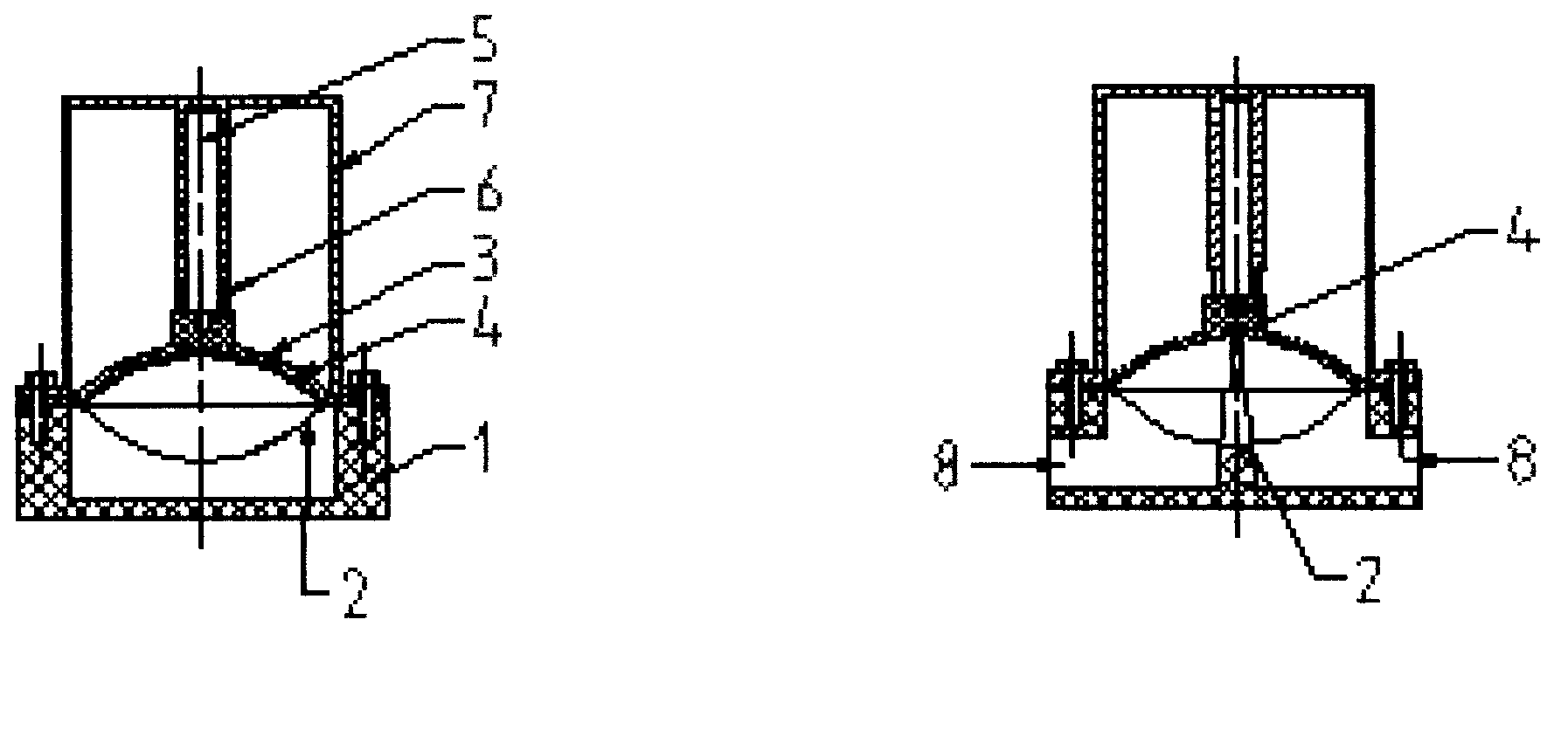
Moreover, since the spring 6 stretches and shrinks, a stroke distance is required, which makes the valve rod 5 extend and the valve body 7 also extend, making the manufacturing process complicated and the cost increased.
And, with the passage of time, the rubber diaphragm begins to age, causing the instability of the reverse deformation shape during operation
During the use of the vacuum diaphragm valve, the concave surface ribs 4 on the concave rubber diaphragm 3 and the base stem 2 of the valve seat 1 are often not tightly sealed, resulting in vacuum leakage and affecting the normal use of the vacuum diaphragm valve.

Method used


Image

  • Inverted vacuum diaphragm valve
  • Inverted vacuum diaphragm valve

Examples


Embodiment

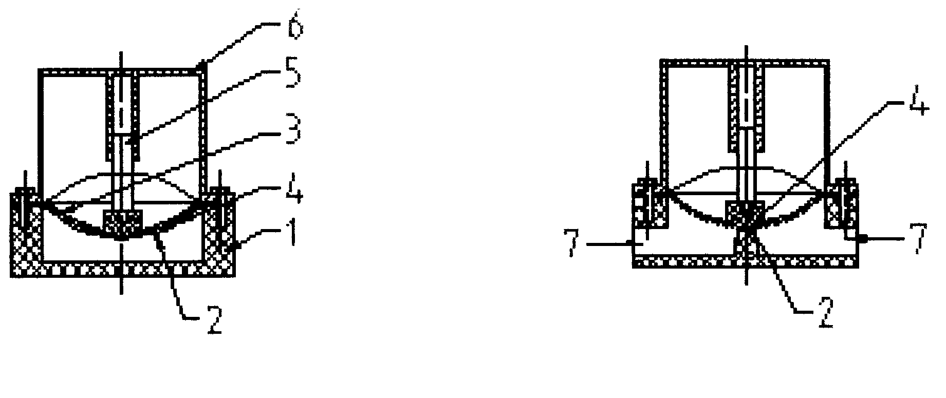
[0015] according to figure 2 As shown, the convex rubber diaphragm 3 is assembled on the valve seat 1 in an inverted way with the concave shape facing upward and the convex shape facing downward, so that the convex surface ribs 4 on the convex rubber diaphragm 3 are aligned with the valve seat 1. When the working program is started, the convex rubber diaphragm 3 and the convex surface rib 4 are sucked up by the vacuum negative pressure to connect the vacuum pipeline system 7. When the working program is stopped, the convex rubber diaphragm 3 The rubber diaphragm 3 and the convex surface ribs 4 naturally fall on the base stem 2 of the valve seat 1 by the force of the downward convex shape, so as to cut off the vacuum pipeline system 7, thereby realizing the opening and closing procedure of the vacuum diaphragm valve .


PUM


Abstract

The invention provides an inverted vacuum diaphragm valve. An inversion fitting process includes the steps: a concave of a rubber diaphragm is placed upward, and a convex of the rubber diaphragm is placed downward; meanwhile, ribs are reversely arranged on the convex surface. A base stem of a valve seat is sealed with the ribs on the convex surface of the rubber diaphragm, so that a method of sealing the rubber diaphragm is simpler and more convenient. The ribs on the convex surface of the rubber diaphragm are normally closed naturally, and primary sealing can be performed on the base stem of the valve seat without pressuring by spring force. A spring is therefore omitted, a valve body and a valve rod are shortened, the structure is more compact and simpler, and the manufacturing cost is lower. The ribs on the convex surface of the rubber diaphragm and the base stem of the valve seat are designed in the same size, design data can be determined without fitting real objects, the ribs and the base stem are hermetically fitted with high reliability, and design difficulty and manufacturing cost are further decreased.

Description

1. Technical field [0001] The technology of the invention relates to a vacuum diaphragm valve, in particular to an inverted vacuum diaphragm valve in which a rubber diaphragm is turned upside down and then vacuum-closed. 2. Background technology [0002] Vacuum diaphragm valve is a valve commonly used in the fields of dairy products, wine industry, bioengineering, food, pharmaceuticals, beverages, cosmetics, water treatment and chemical industry. according to figure 1 As shown: the conventional vacuum diaphragm valve has a valve seat 1, a base stem 2, a concave rubber diaphragm 3, a concave surface rib 4, a valve stem 5, a spring 6, a valve body 7, and a vacuum piping system 8, etc. The vacuum diaphragm valve uses the force of the spring 1 and the vacuum suction to directly press the concave rubber diaphragm 3 and the concave surface rib 4 on the base stem 2 of the valve seat 1 to cut off or connect the vacuum pipeline system 8 . The vacuum diaphragm valve is compact and ...

Claims


Application Information

Patent Timeline
IPC IPC(8): F16K7/14
CPCF16K7/17
Inventor 宋志远罗贾蓉
Owner 宋志远
Learn More