Water vortex splashing and filtering device

A filter device and water swirl technology, which is applied in combined devices, suction filters, and dispersed particle separation, can solve problems such as poor gas filtration effect, and achieve the effects of enhanced capture ability, strong fusion ability, and strong capture ability

Active Publication Date: 2010-03-17
BINZHOU DAYOU NEW ENERGY DEV
View PDF1 Cites 2 Cited by
  • Summary
  • Abstract
  • Description
  • Claims
  • Application Information

AI Technical Summary

Problems solved by technology

[0006] In order to solve the above-mentioned problem of poor gas filtration effect, the object of the present invention is to provide a water swirl splash filter device for high-precision filtration of gas

Method used


Image

  • Water vortex splashing and filtering device
  • Water vortex splashing and filtering device
  • Water vortex splashing and filtering device

Examples


Embodiment 1

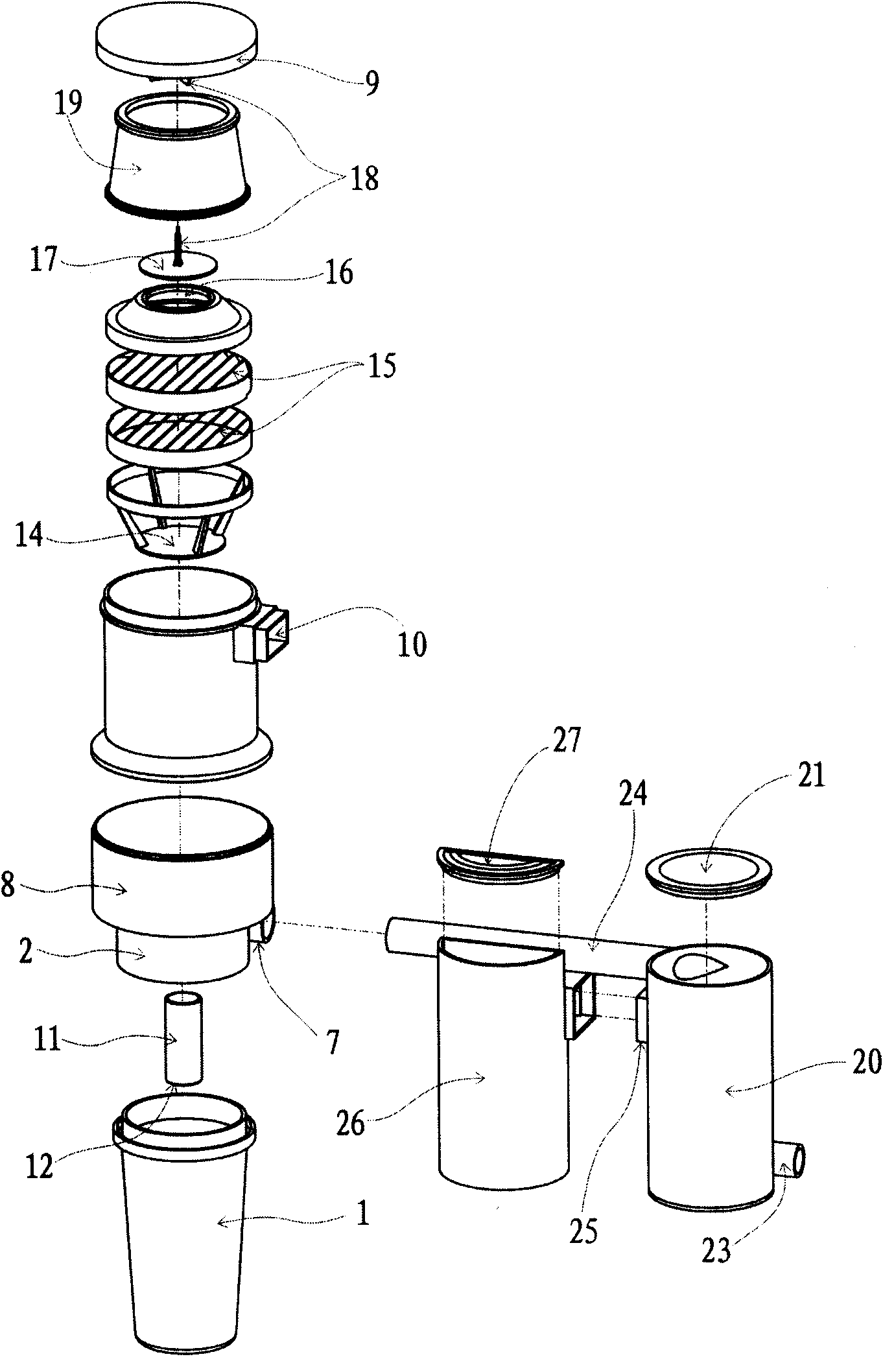
[0038]Embodiments of the present invention are as figure 1 , figure 2 As shown, it includes coarse filter device, air intake pipe (7), water swirl filter part, suction air pipe (11), splash filter part, splash baffle (14), splash-proof component, moisture-proof device, protective net cover; the water whirl filter part is composed of the water whirl chamber (1) and the water whirl chamber upper cover (2), and the lower part of the water whirl chamber (1) is provided with an annular isolation plate (3) ), a deposition chamber (4) is formed between the ring-shaped separating plate (3) and the bottom of the hydrovortex chamber (1), and the side wall of the hydrovortex chamber loam cake (2) is provided with a gas cutout (6), and the gas cutout The inlet (6) is connected with an air inlet pipe (7); the splash filter part is composed of a splash chamber (8) and a splash chamber upper cover (9), and the splash chamber upper cover is placed on the side wall of the splash chamber (8)....

Embodiment 2

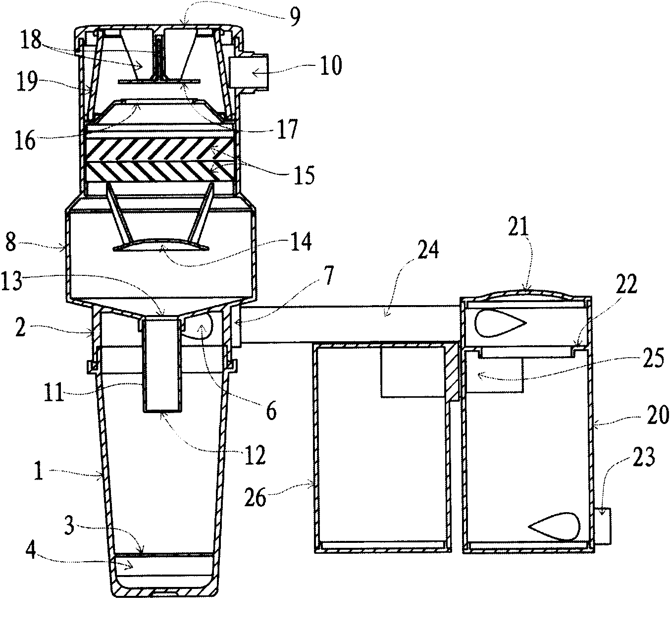
[0053] The second embodiment of the present invention is as image 3As shown, it includes an air inlet pipe (7), a water swirl filter part, a suction air duct (11), a splash filter part, a splash baffle (14), and a splash prevention member; ) and the water swirl chamber upper cover (2), the bottom of the water swirl chamber (1) is provided with an annular isolation plate (3) connected to the side wall of the water swirl chamber (1), the annular isolation plate (3) and the water swirl A deposition chamber (4) is formed between the bottoms of the chamber (1), the diameter of the deposition chamber (4) is greater than the diameter of the annular separation plate (3), and the side wall of the hydrovortex chamber loam cake (2) is provided with a gas cutout (6 ), the gas inlet (6) is connected with the air inlet pipe (7); the splash filter part is composed of the splash chamber (8) and the splash chamber upper cover (9), and is above the splash chamber upper cover (9) An air outlet...

Embodiment 3

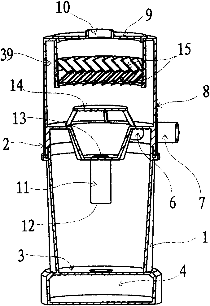
[0057] The third embodiment of the present invention is as Figure 4 As shown, it includes an air inlet pipe (7), a water swirl filter part, a suction air duct (11), a splash filter part, a splash baffle (14), and a splash prevention member; ) and the water swirl chamber upper cover (2), the side wall of the water swirl chamber upper cover (2) is provided with a gas incision (6), and the gas incision (6) is connected with an air inlet pipe (7); the splash The filter part is composed of a splash chamber (8) and a splash chamber upper cover (9), and an air outlet (10) is arranged above the splash chamber upper cover (9); the bottom of the splash chamber (8) is formed by a water swirl chamber The center of the upper cover (2) sinks into the water swirl chamber (1), and one end of the suction air pipe (11) passes through the center of the bottom of the splash chamber (8) and extends into the swirl chamber (1) to form a port One (12), the other end forms port two (13) at the cente...


PUM


Abstract

The invention discloses a water vortex splashing and filtering device, which is characterized by comprising a water vortex filtering part of a gas inlet pipeline, a splashing and filtering part, a water pumping wind pipe and a splashing baffle plate, wherein the water vortex filtering part is a cavity which consists of a water vortex chamber and an upper cover of the water vortex chamber and has acircular cross section; a gas incisive opening is arranged on the side wall of the water vortex chamber or the side wall of the upper cover of the water vortex chamber, and is connected with the airinlet pipeline; the splashing and filtering part is a cavity which consists of a splashing chamber and an upper cover of the splashing chamber, and a wind outlet is arranged on the side wall of the cavity or an upper cover plate of the upper cover of the splashing chamber; one end of the water pumping wind pipe passes through the center of the upper cover plate of the upper cover of the water vortex chamber and extends into the water vortex chamber to form a port I, and the other end of the water pumping wind pipe is communicated with the splashing and filtering part and extends into the cavity to form a port II; and the splashing baffle plate is arranged between the port II and the wind outlet. The water vortex splashing and filtering device firstly carries out centrifugal filtration by water vortex, and then uses excess water forming the water vortex to carry out splashing and filtration, so the water has two purposes, and the filtration precision is high.

Description

technical field [0001] The invention relates to a filtering device, in particular to a water swirling and splashing filtering device, which adopts liquid as the filtering and separating material, and can filter and separate one or several components to be separated from the gas and keep them in the liquid. For example, it is applied to vacuum cleaners and teaching blackboard dust collectors as filter components to realize the separation and filtration of dust in the gas. Background technique [0002] In daily life and production, the problem of gas filtration is often encountered, and it is required to filter and separate one or several components in the gas. At present, the mainstream technology of filter components used in existing products such as vacuum cleaners in the market is to use microporous filtration to separate There is also a way of filtering and separating materials, and there is another way of cyclone filtering. [0003] Use microporous filtration separation...

Claims


Application Information

Patent Timeline
IPC IPC(8): B01D50/00A47L9/16A47L9/18
Inventor 郑海涛
Owner BINZHOU DAYOU NEW ENERGY DEV
Why Eureka
Try Eureka