Operation controller of elevator system

An operation control, elevator system technology, applied in transportation and packaging, elevators in buildings, etc., can solve the problem of not solving the door opening time, shortening the door opening time, and the user not catching up with the ride.

Inactive Publication Date: 2010-03-17
TOSHIBA ELEVATOR KK
View PDF1 Cites 6 Cited by
  • Summary
  • Abstract
  • Description
  • Claims
  • Application Information

AI Technical Summary

Problems solved by technology

[0010] However, when the door opening time is uniformly shortened, there is a problem that the user frequently misses the ride.
In addition, in the method of pressing the door-closing button in the car by the user who has gotten into the car when the user's boarding has been interrupted before the prescribed door-opening time has elapsed, pressing the door-closing bu...

Method used


Image

  • Operation controller of elevator system
  • Operation controller of elevator system
  • Operation controller of elevator system

Examples


no. 1 Embodiment approach

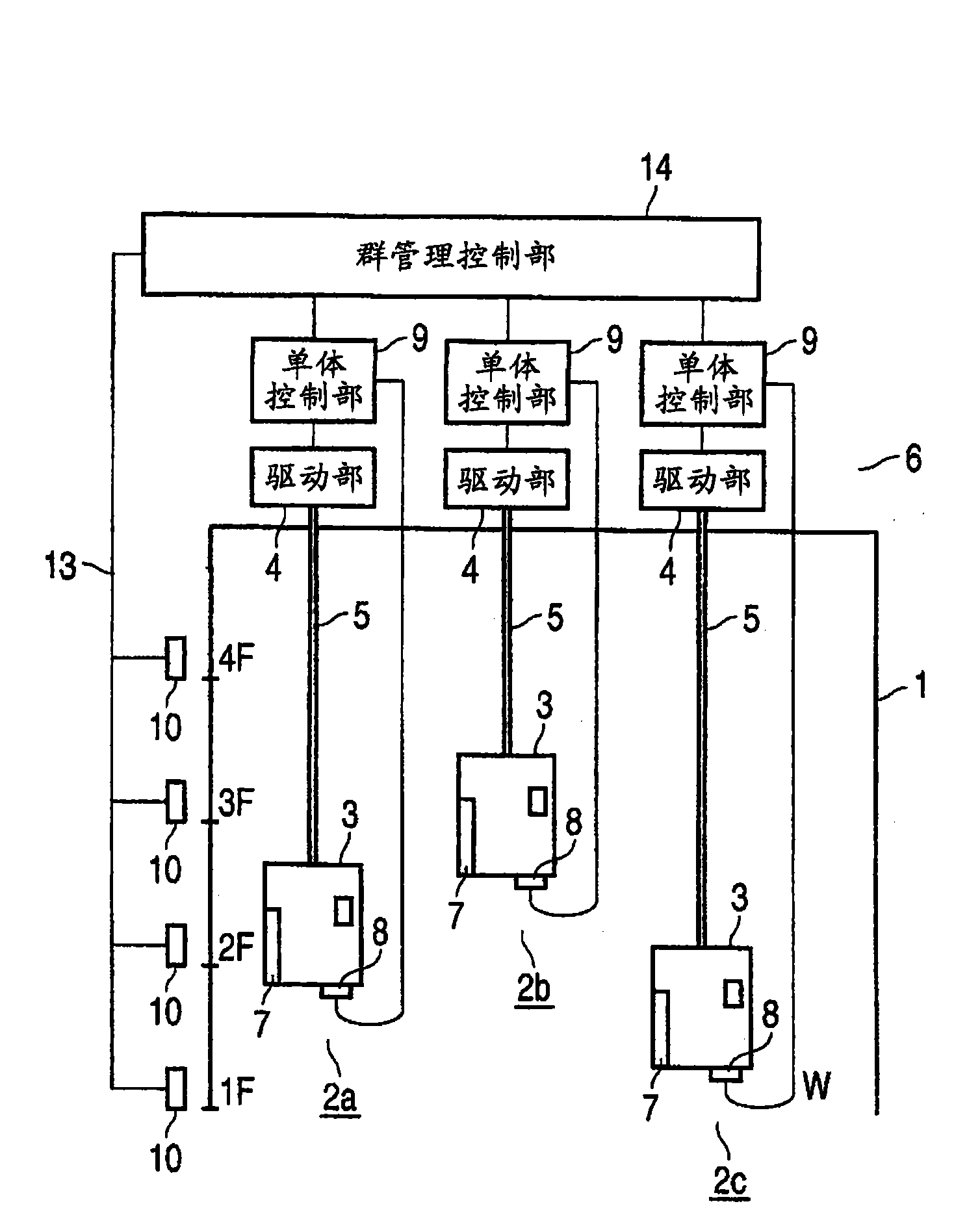
[0031] figure 1 It is a schematic configuration diagram of an elevator system incorporating an operation control device according to the first embodiment of the present invention. A plurality of elevators 2a (No. 1 machine), 2b (No. 2 machine), and 2c (No. 3 machine) are installed in the elevator road 1 of the building. In each of the elevators 2a, 2b, and 2c, a drive unit 4 including a motor and a winding machine provided in the machine room 6 on the upper side of the hoistway 1 is used to suspend the car 3 on the main rope 5.

[0032] A door 7 is provided in each car 3. A load meter 8 is installed under the floor of the car 3. The load meter 8 is initially set to load W=0 when there is no user in the car 3. The load W measured by the load meter 8 is input to the individual control unit 9 of the elevators 2a to 2c.

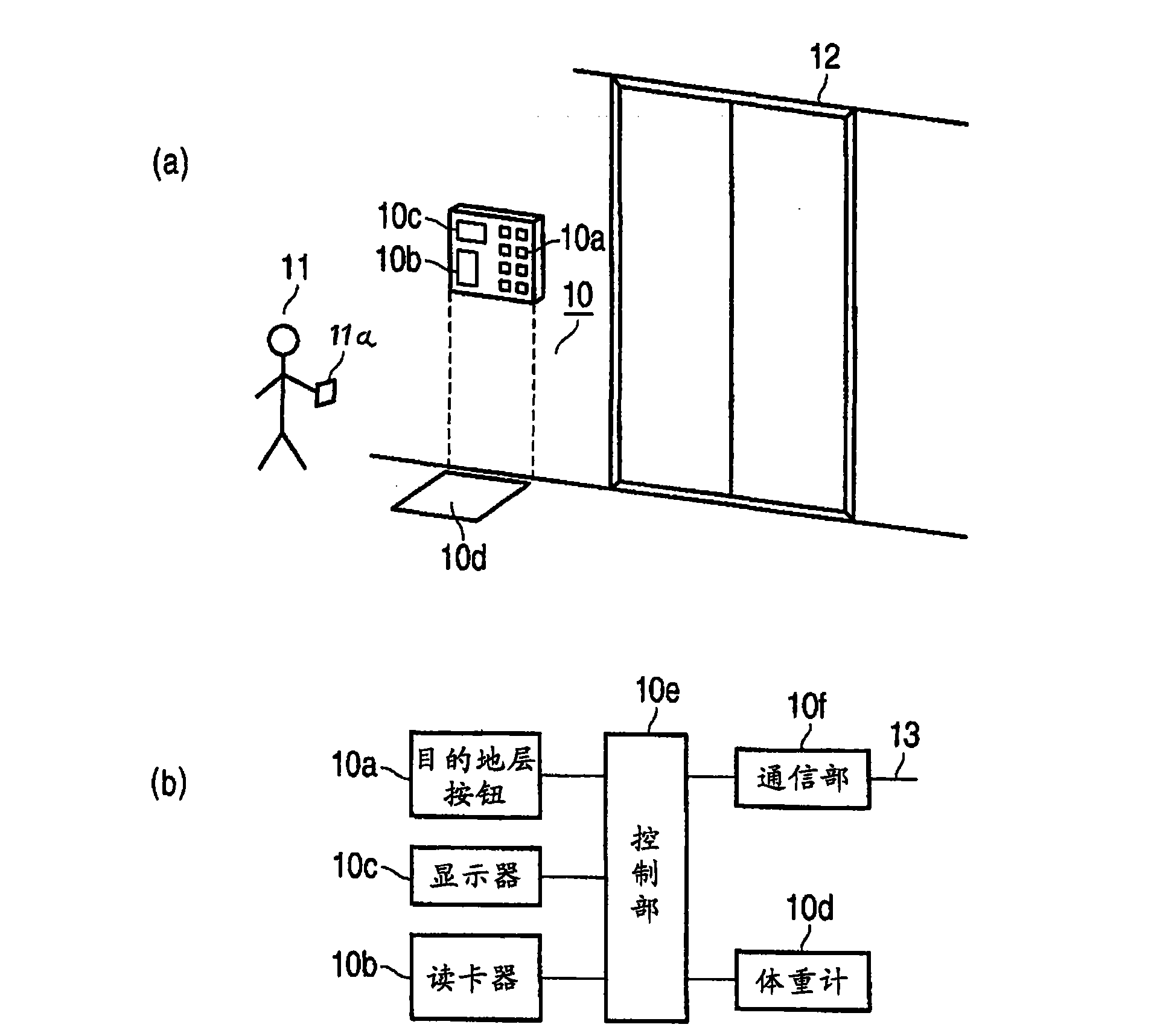
[0033] Set up in the elevator hall on each floor where the elevator system is installed figure 2 (a), (b) The destination layer designation device 10 is shown. S...

no. 2 Embodiment approach

[0057] Figure 8 It is a block diagram showing the schematic configuration of the group management control unit and the individual control unit in the elevator system incorporating the operation control device according to the second embodiment of the present invention. Right and Figure 4 The same parts of the group management control unit and the individual control unit of the first embodiment shown are denoted by the same reference numerals, and detailed descriptions of overlapping parts are omitted. In addition, the overall diagram of the elevator system of the second embodiment and figure 1 The first embodiment shown is substantially the same, so the description is omitted.

[0058] The group management control unit 14 of the second embodiment has substantially the same configuration as the group management control unit 14 of the first embodiment. In addition, in this second embodiment, a cell control unit 9a is provided instead of the cell control unit 9 used in the first e...

no. 3 Embodiment approach

[0078] Picture 11 It is a schematic configuration diagram of an elevator system incorporating an operation control device according to the third embodiment of the present invention. Right and figure 1 The same parts in the elevator system of the first embodiment shown are denoted by the same symbols. Therefore, detailed description of overlapping parts is omitted.

[0079] In this third embodiment, as the destination layer specifying device, the Picture 12 The illustrated personal authentication reading device that reads the IC tag 28 wirelessly is the wireless reading device 26. The internal memory 27 of the IC tag 28 stores a user name, a user ID, and two use permission layers. The IC tag 28 can be placed in the pocket of the user 11 of the building, for example.

[0080] In addition, the user 11 of the building carries the IC tag 28 with him, and when passing through the vicinity of the wireless reading device 26, the user name, user ID, and two license layers stored in the I...


PUM


Abstract

The present invention provides an operation controller of an elevator system, which moves the elevator cage to an appointed storey according to the operation of an appointed target storey of the useron a target storey appointer (10) set on an elevator hall of each storey of the building. The invention is characterized in that the operation controller of the elevator system comprises the followingcomponents: an using information output part (10e) which outputs the body weight measured by a body weight scale (10d) that is provided in the target storey appointer, target storey and elevator embarkation calling as the using information for outputting; a load meter (8) which is provided in the cage for measuring the load of all users in the cage; an embarkation load calculation part (9) whichcalculates the total embarkation load of the users which embark the cage from a corresponding storey according to the using information from the target storey appointer; a before-stopping load readingpart (22) which reads the load which aims at the called cage at the elevator embarkation position and is just before stopping as the load before stopping; and a door closing determination part (23) which calculates the load reduction amount generated by the elevator user when the cage is stopped, causes the door close the door and move to the target storey of the using information when the load of the load meter in cage stopping falls into the permissible range of a value obtained through subtracting the value of load reduction amount from the load before stopping, and adding the obtained value with the embarkation load.

Description

Technical field [0001] The present invention relates to an elevator system installed in an office building of a company, etc., which is not used by an unspecified plurality of people, but is used by a predetermined specific user, and particularly relates to operation control of an elevator system that improves the operation efficiency for users Device. Background technique [0002] Generally, the elevator system installed in each building consists of multiple elevators. In addition, in the normal automatic operation mode, when the user presses the boarding place button in the boarding area (parking area, elevator room) on each floor, selecting (allocating) multiple elevators can respond in the shortest time The car of the elevator of this number will open the door when the elevator car of this number arrives (arrives) at the floor with the button of the elevator. And, when a user waiting in the elevator hall gets in (enters), the door is closed. And, when the user in the car p...

Claims


Application Information

Patent Timeline
IPC IPC(8): B66B13/14
Inventor 真锅嘉章
Owner TOSHIBA ELEVATOR KK
Why Eureka
Try Eureka