
Compressing device for clutch

A compression device and clutch technology, applied in clutches, friction clutches, mechanically driven clutches, etc., can solve the problems of inability to achieve precise torque control and inability to accurately control the movement of clutch discs, and achieve the effect of precise control of torque transmission

Active Publication Date: 2011-08-10
WUHU WANLIYANG TRANSMISSION CO LTD
View PDF0 Cites 0 Cited by
  • Summary
  • Abstract
  • Description
  • Claims
  • Application Information

AI Technical Summary

Problems solved by technology

However, the above-mentioned mechanical pressing device mainly relies on springs (coil springs or diaphragm springs) and release levers to control the separation or compression of the clutch plates, and cannot accurately control the movement of the clutch plates, that is, the precise control of the transmitted torque cannot be achieved. , so it is not suitable for application in all-wheel drive vehicles with intelligent torque management

Method used


Image

  • Compressing device for clutch
  • Compressing device for clutch
  • Compressing device for clutch

Examples


Embodiment 1

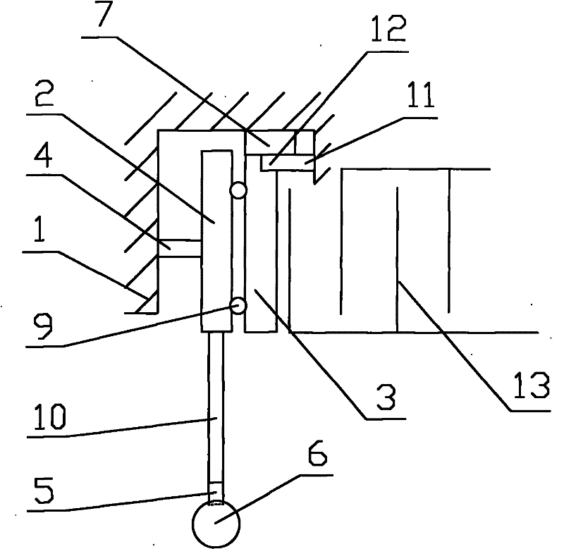
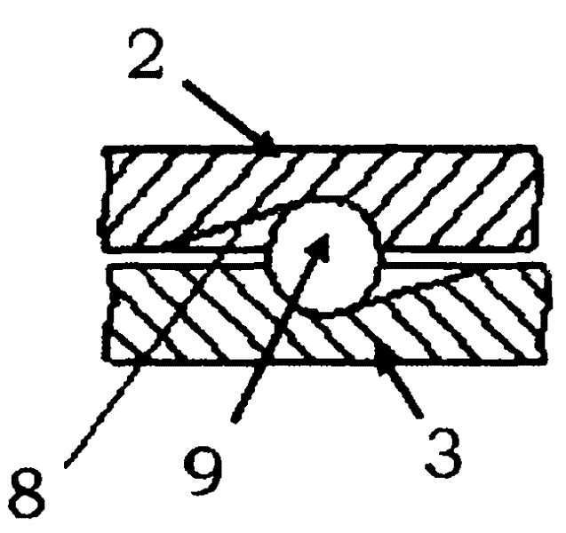
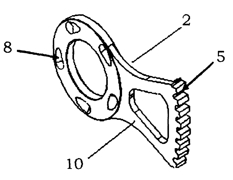
[0017] As shown in the figure, the clutch pressing device of this embodiment includes a housing 1, a main pressure plate 2 and a slave pressure plate 3, the hubs of the main pressure plate 2 and the slave pressure plate 3 are opposite, and the main pressure plate 2 The rotating shaft 4 is fixed to the housing 1, the main pressure plate 1 is axially limited to the rotating shaft 4 and can rotate around the rotating shaft 4; the bottom of the main pressure plate 1 is provided with a transmission rod 10, and the bottom of the transmission rod 10 is provided with a worm gear 5, so The worm gear tooth 5 is matched with a control shaft 6 of a worm structure; the slave pressure plate 3 is arranged on the side of the main pressure plate 2, and is installed on the housing 1 through a spline 7; the main pressure plate 2 and the slave pressure plate The opposite sides of the disc 3 are all provided with track grooves 8, and the track grooves 8 are located on the circumference with the cen...


PUM


Abstract

The present invention provides a compressing device for a clutch which can accurately control the movement of clutch plate. The compressing device comprises a shell, a main pressing plate and a secondary pressing plate. The center of the main pressing plate is opposite to the center of the secondary pressing plate. The main pressing plate is fixed with the shell by a rotating shaft, is axially limited on the rotating shaft and can rotate around the rotating shaft. A gear, which is matched with a control shaft having a gear or screw threads, is disposed on the bottom of the main pressing plate. The secondary pressing plate is disposed on the side face of the main pressing plate and is mounted on the shell by a spline. The opposite side faces of the main pressing plate and the secondary pressing plate are provided with a rail slot which is on the circumference using the center of the main and secondary pressing plates as the center of a circle. The radian thereof is as same as the radian of the circumference of the main and secondary pressing plates. The depth of the rail slot gradually decreases from one end to the other end. The decreasing directions of the depth of the rail slot on the main and secondary pressing plates are reverse. A steel ball is disposed between the opposite deeper parts of the rail slots corresponding to the main and secondary pressing plates. Furthermore, a pressure sensor is arranged between one side that the secondary pressing plate is far away from the main pressing plate and the shell.

Description

technical field [0001] The invention belongs to the technical field of automobile manufacturing, and in particular relates to a pressing device of a clutch. Background technique [0002] The traditional clutch pressing device generally adopts mechanical structure, electromagnetic structure and hydraulic structure. Its main function is to provide pressing force for the clutch plate. Under different pressing forces, the clutch can transmit different torques. Among them, the mechanical Because of the advantages of high work reliability, simple structure, easy manufacture, and relatively low cost, the type compression device is the most widely used. However, the above-mentioned mechanical pressing device mainly relies on springs (coil springs or diaphragm springs) and release levers to control the separation or compression of the clutch plates, and cannot accurately control the movement of the clutch plates, that is, the precise control of the transmitted torque cannot be achiev...

Claims


Application Information

Patent Timeline
Patent Type & Authority Patents(China)
IPC IPC(8): F16D13/70
Inventor 钱建功董宾吴罡白靖哲
Owner WUHU WANLIYANG TRANSMISSION CO LTD
Learn More