Main-contact electrical-contact state on-line detector for low-voltage circuit breaker

A low-voltage circuit breaker and electrical contact technology, used in circuit breaker testing, measuring devices, instruments, etc., can solve the problem of inability to reflect the electrical contact state of the main contact of the low-voltage circuit breaker in real time and accurately, and achieve easy implementation and guarantee. The effect of electrical isolation

Active Publication Date: 2012-05-02
JIANGSU TRIGIANT TECH
View PDF6 Cites 0 Cited by
  • Summary
  • Abstract
  • Description
  • Claims
  • Application Information

AI Technical Summary

Problems solved by technology

Although there are patents related to the related technology of the contact loss indicator, such as the Chinese patent No. "ZL87105402" titled "Solid circuit tripping device for circuit breaker with contact loss indicator", the contact loss The value is estimated based on the maximum value of the cut-off current. The degree of contact loss is represented by the result of successive addition of contact loss values. It is not the result of actual measurement, and cannot reflect the main contact of the low-voltage circuit breaker online, in real time and accurately. electrical contact state

Method used


Image

  • Main-contact electrical-contact state on-line detector for low-voltage circuit breaker
  • Main-contact electrical-contact state on-line detector for low-voltage circuit breaker
  • Main-contact electrical-contact state on-line detector for low-voltage circuit breaker

Examples


Embodiment Construction

[0016] The following is the technical solution further described in conjunction with the accompanying drawings and embodiments.

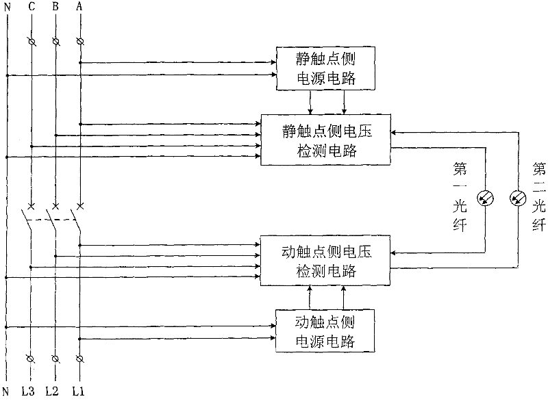
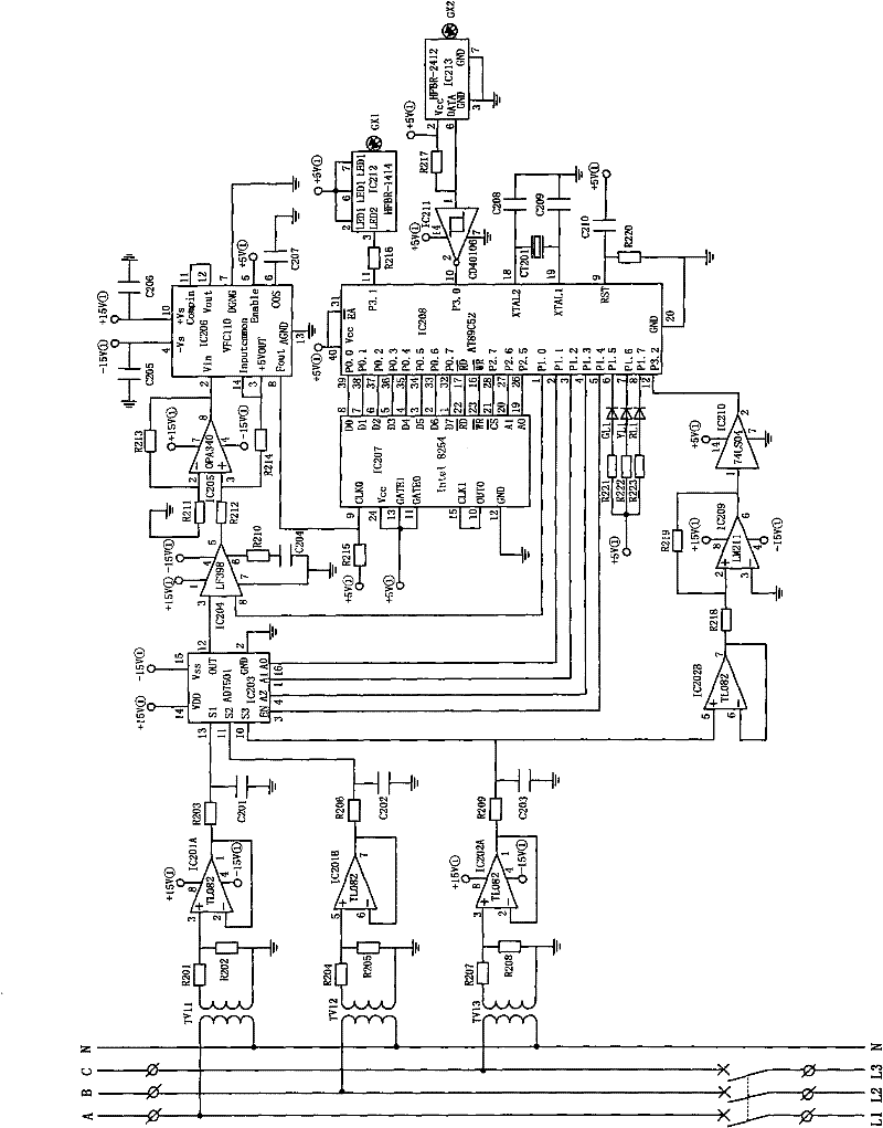
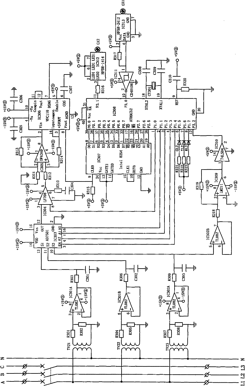
[0017] see figure 1 , an on-line detection device for the electrical contact status of the main contacts of a low-voltage circuit breaker, a static contact side voltage detection circuit and a static contact side power supply circuit are arranged at one end of the low-voltage circuit breaker connected to the power line power supply, and a static contact side power supply circuit is installed at one end of the low-voltage circuit breaker connected to the power line load Set the voltage detection circuit on the moving contact side and the power supply circuit on the moving contact side. The voltage detection circuit on the static contact side and the voltage detection circuit on the moving contact side transmit data through optical fibers. Circuit power supply, the power supply circuit on the moving contact side alone supplies power to the voltage de...


PUM


Abstract

The invention relates to a main-contact electrical-contact state on-line detector for a low-voltage circuit breaker, which comprises a static-contact side voltage detection circuit, a static-contact side power circuit, a traveling-contact side voltage detection circuit and a traveling-contact side power circuit, wherein the static-contact side voltage detection circuit and the static-contact sidepower circuit are arranged at the end of an electric line power source of a low-voltage circuit breaker; the traveling-contact side voltage detection circuit and the traveling-contact side power circuit are arranged at the end of an electric line load of the low-voltage circuit breaker; the static-contact side voltage detection circuit and the traveling-contact side voltage detection circuit transmit data through optical fibers; the static-contact side power circuit independently supplies power to the static-contact side voltage detection circuit, and the traveling-contact side power circuit independently supplies power to the traveling-contact side voltage detection circuit; and the traveling-contact side voltage detection circuit transmits the collected electric line phase voltage data to the static-contact side voltage detection circuit through optical fibers. The detector has the advantage of convenient and safe operation, accurately measures the voltage difference between the static contact and the traveling contact of the low-voltage circuit breaker on line in real time, can judge the electric contact state of the main contact of the low-voltage circuit breaker, and ensure the electrical insulation of the static contact side and the traveling contact side when the low-voltage circuit breaker is in the off state.

Description

technical field [0001] The invention relates to an on-line detection device for the electrical contact state of a main contact of a low-voltage circuit breaker. Background technique [0002] The main contact of the low-voltage circuit breaker includes two parts, the static contact and the moving contact. The static contact is connected to the power line power supply, and the moving contact is connected to the power line load. An arc is generated between the moving contact and the moving contact due to cutting off or connecting the current. Although the low-voltage circuit breaker has various measures to extinguish the arc, the arc always exists and causes different degrees of metal loss in the main contact. With the increase of the number of opening and closing actions performed by the low-voltage circuit breaker, the metal loss of the main contact increases gradually, the contact resistance of the static contact and the moving contact becomes larger, and the voltage of the ...

Claims


Application Information

Patent Timeline
Patent Type & Authority Patents(China)
IPC IPC(8): G01R31/327G01R19/165G08C23/06
Inventor 李智超罗野
Owner JIANGSU TRIGIANT TECH
Why Eureka
Try Eureka