Control device applied in power factor correction power converter and control method thereof

A technology of power factor correction and power converter, which is applied in the direction of output power conversion device, high-efficiency power electronic conversion, control/regulation system, etc., and can solve the problems of high-frequency switching energy loss, increase, and increased THD

Active Publication Date: 2013-07-10
LEADTREND TECH
View PDF6 Cites 0 Cited by
  • Summary
  • Abstract
  • Description
  • Claims
  • Application Information

AI Technical Summary

Problems solved by technology

[0007] However, even if the on-time increases slightly with the shortening of the off-time, once the off-time is too short, it will cause unnecessary high-frequency switching energy loss (switching loss)
Moreover, the on-time changes with the off-time (off-time), which may increase the THD instead

Method used


Image

  • Control device applied in power factor correction power converter and control method thereof
  • Control device applied in power factor correction power converter and control method thereof
  • Control device applied in power factor correction power converter and control method thereof

Examples


Embodiment Construction

[0027] The content of the present invention will be explained below through examples. However, the embodiments of the present invention are not intended to limit the present invention to be implemented in any specific environment, application or special method as described in the embodiments. Therefore, the descriptions about the embodiments are only for the purpose of explaining the present invention, not limiting the present invention. It should be noted that in the following embodiments and drawings, elements not directly related to the present invention have been omitted and not shown. For technical convenience, components that are the same or similar, or have similar functions, will use the same component symbols when explaining. However, it should be emphasized that the same labeled elements in different embodiments can be implemented by different elements.

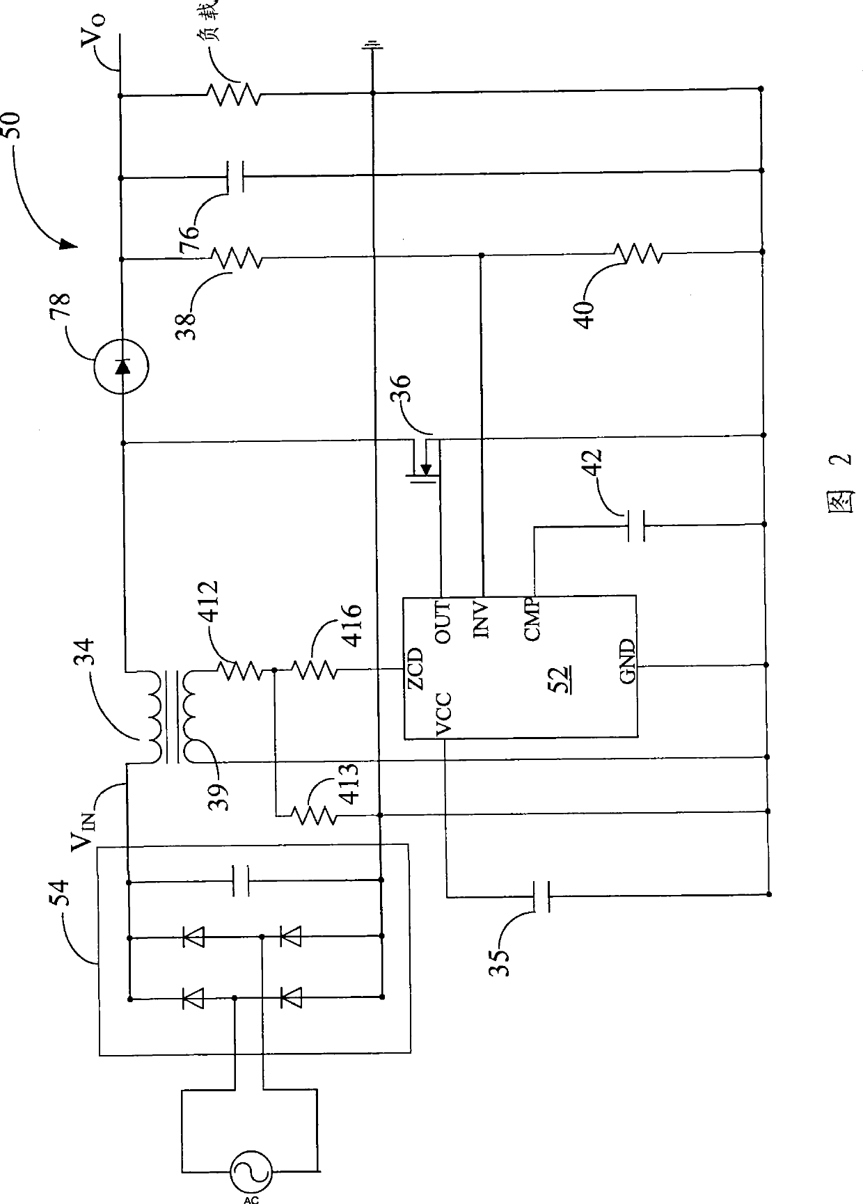
[0028] Please refer to FIG. 2 , which is an AC-to-DC converter 50 implemented according to an embodiment of the...


PUM


Abstract

The invention relates to a control device applied in a power factor correction power converter and a control method thereof. The control device is used for reducing the change rate of a reference signal with an ascending part and a descending part when an input voltage approaches zero potential. When a main winding releases approximately all stored energy and the descending part of the reference signal reaches a condition, the control device turns on a changeover switch to increase the stored energy of the main winding.

Description

technical field [0001] The present invention relates to an AC to DC converter architecture, in particular to an AC to DC converter architecture with power factor correction (power factor correction, PFC). Background technique [0002] In most AC-to-DC converters, it is desirable to have the entire circuit exhibit a purely resistive behavior with respect to the AC input voltage. For this reason, many active PFC architectures have been developed today, and these PFC architectures can generate a corresponding AC input current when receiving an AC input voltage. [0003] For PFC, it is very important to generate a sine wave current with very low total harmonic distortion (THD). THD and power factor represent the operational performance of the PFC circuit. The highest value of power factor is 1, and in general practice, THD is acceptable as long as it is lower than 15%. [0004] For example, US Patent Nos. 7,375,995, 7,397,678, re40016, and 7,295,452, etc. all disclose part of...

Claims


Application Information

Patent Timeline
Patent Type & Authority Patents(China)
IPC IPC(8): H02M1/42G05F1/70
CPCY02B70/126Y02B70/10Y02P80/10
Inventor 吴宗修
Owner LEADTREND TECH
Why Eureka
Try Eureka