Energy storage sleeve and energy storage electric water heater

An electric water heater and casing technology, which is applied in the fields of energy saving, sanitary products and energy storage, and water heaters, can solve the problems of high price, troublesome installation, large volume, etc., and achieve the effects of freeing space, large energy storage and simple structure.

Inactive Publication Date: 2015-11-25
李渊
View PDF0 Cites 7 Cited by
  • Summary
  • Abstract
  • Description
  • Claims
  • Application Information

AI Technical Summary

Problems solved by technology

[0005] In the existing market, there are very few civil electric energy storage water heaters, and the traditional water storage water heaters are too bulky, especially large-capacity water heaters; while air energy water heaters are energy-saving, but they are expensive, noisy, troublesome to install, Disadvantages such as large volume, especially when the external ambient temperature is too low, the operation situation will be very difficult

Method used


Image

  • Energy storage sleeve and energy storage electric water heater
  • Energy storage sleeve and energy storage electric water heater
  • Energy storage sleeve and energy storage electric water heater

Examples


Embodiment 1

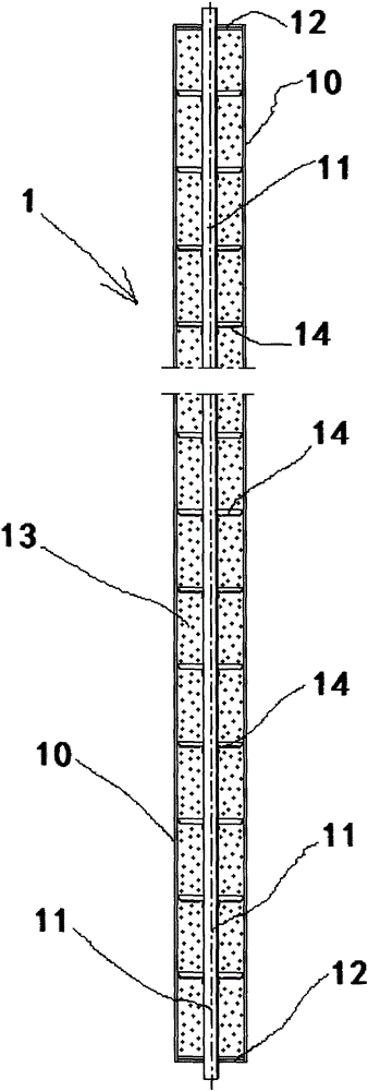
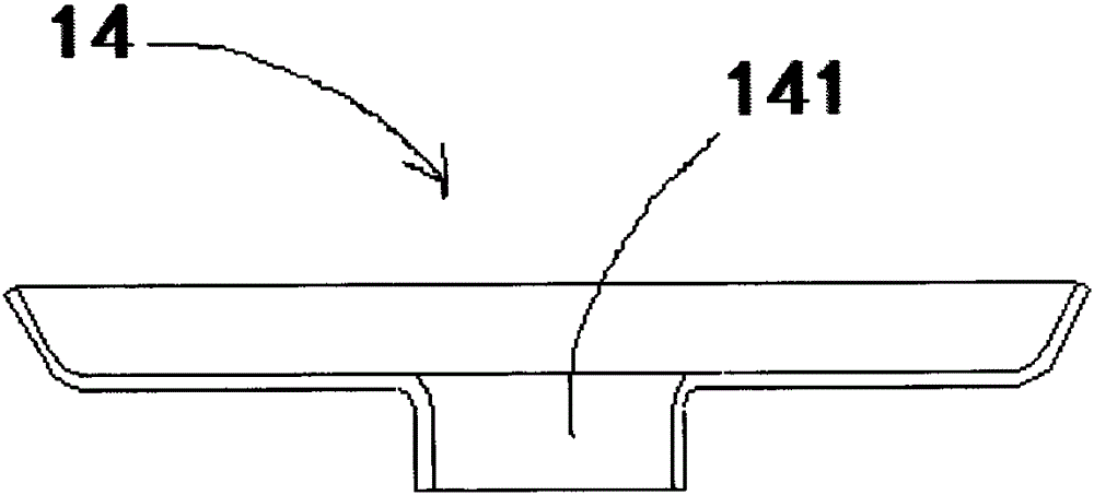
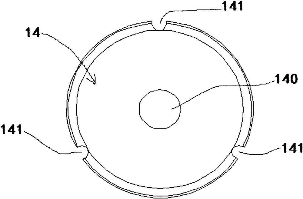
[0038] Such as figure 1 , figure 2 with image 3 As shown, an energy storage sleeve includes an energy storage sleeve body 1, and the energy storage sleeve body 1 includes an outer tube 10, an inner tube 11, a cover 12, a phase change energy storage material 13 and an outer wall of the inner tube 11. The fins 14 on the top, wherein, the outer tube 10 and the inner tube 11 are set together in concentric circles and the two ports are respectively sealed by the cover 12, and the two ports of the inner tube 11 respectively pass through the body of the cover 12, and the outer A closed accommodating chamber 15 is formed between the inner wall of the tube 10 and the outer wall of the inner tube 11, the phase change energy storage material 13 is arranged in the accommodating chamber 15, the outer wall of the inner tube 11 is provided with fins 14, and the fins 14 and the inner tube The connection of 11 adopts interference fit or through high-frequency welding.

[0039] The fins 14...

Embodiment 2

[0041] Such as figure 1 , figure 2 , image 3 , Figure 4 , Figure 5 , Figure 7 , Figure 8 , Figure 9 , Figure 10 ,with Figure 11 As shown, an energy-storage electric water heater includes an energy-storage electric water heater body 2, and the energy-storage electric water heater body 2 is composed of a thermal insulation shell 3, an electric heat storage heat exchange body 4 and a temperature control device 5 arranged in the thermal insulation shell 3 Composition, the electrothermal energy storage heat exchange body 4 includes the energy storage sleeve body 1, the inner pipe connecting elbow 6, the electric heating element 7, and a cold water interface 30 and a hot water interface 31 are arranged on one side of the heat preservation shell 3, adjacent The two ports of the energy storage casing body 1 are connected through a 180° inner pipe connection elbow 6, and form a heat exchange body channel 8 in an S-shaped direction. One end of the heat exchange body cha...

Embodiment 3

[0045] Such as figure 1 , figure 2 , image 3 , Figure 12 , Figure 13 , Figure 14 with Figure 15 As shown, an energy-storage electric water heater includes an energy-storage electric water heater body 2, and the energy-storage electric water heater body 2 is composed of a thermal insulation shell 3, an electric heat storage heat exchange body 4 and a temperature control device 5 arranged in the thermal insulation shell 3 Composition, the electrothermal energy storage heat exchange body 4 includes the energy storage sleeve body 1, the inner pipe connecting elbow 6, the electric heating element 7, and a cold water interface 30 and a hot water interface 31 are arranged on one side of the heat preservation shell 3, adjacent The two ports of the energy storage casing body 1 are connected through a 180° inner pipe connection elbow 6, and form a heat exchange body channel 8 in an S-shaped direction. One end of the heat exchange body channel 8 is connected to the cold water ...


PUM


Abstract

An energy storage sleeve comprises an outer pipe, an inner pipe, sealing covers, phase change energy storage materials and fins arranged on the outer wall of the inner pipe; the inner pipe is sleeved with the outer pipe in a concentric mode, and the two end openings of the outer pipe are sealed through the sealing covers; the two end openings of the inner pipe penetrate through the sealing covers respectively, so that a closed containing cavity is formed between the inner wall of the outer pipe and the outer wall of the inner pipe; the phase change energy storage materials are arranged inside the containing cavity; the disc-shaped fins are arranged on the outer wall of the inner pipe. The energy storage electric water heater is composed of a heat preservation shell, an electric energy storage heat exchange body and a temperature control device; the electric energy storage heat exchange body comprises the energy storage sleeves, inner pipe connecting bends and an electrical heating element; a cold water port and a hot water port are formed in one side edge of the heat preservation shell; the two end openings of every two adjacent energy storage sleeves are connected through the corresponding inner pipe connecting bend, and an S-shaped heat exchange body channel is formed; one end of the heat exchange body channel is connected with the cold water port, and the other end of the heat exchange body channel is connected with the hot water port; the electrical heating element is arranged at the end of the electric energy storage heat exchange body or on the outer wall of the corresponding energy storage sleeve.

Description

technical field [0001] The invention belongs to the technical field of water heaters, bathroom products, energy storage and energy saving, and in particular relates to the technology of an energy storage casing and an energy storage electric water heater. Background technique [0002] With the improvement of people's living standards and the comfort requirements for working and living environments, the consumption of electric energy has increased significantly, resulting in excessive energy consumption, increased environmental pollution, excessive peak and valley loads on the power grid, and serious shortage of power supply during peak loads. Such as the increase of building energy consumption. At present, the building energy consumption in developed countries in Europe and the United States has reached 40% of the total energy consumption of the whole society. In my country, building energy consumption accounts for about 30% of the total energy consumption in the country. With...

Claims


Application Information

Patent Timeline
Patent Type & Authority Applications(China)
IPC IPC(8): F28D20/02F24H7/02
CPCY02E60/14
Inventor 李渊
Owner 李渊
Why Eureka
Try Eureka