
LACP MAD detection method and device thereof

A technology of equipment and detection domain, applied in the field of communication, can solve the problem that the IRF1 stacking system cannot perform normal detection and so on

Active Publication Date: 2010-03-17
NEW H3C TECH CO LTD
View PDF0 Cites 28 Cited by
  • Summary
  • Abstract
  • Description
  • Claims
  • Application Information

AI Technical Summary

Problems solved by technology

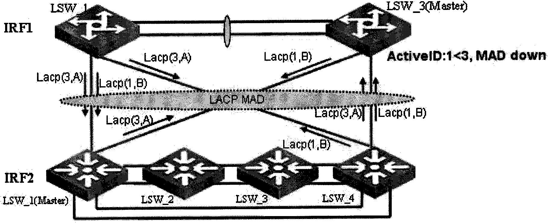
When MAD detection is enabled on the aggregation ports on the IRF1 and IRF2 sides at the same time, the devices in IRF1 and IRF2 periodically send and receive LACPDU packets through the member ports of the aggregation link, so that the devices in IRF1 and IRF2 may receive another stack system For example, when LSW3 receives an LACPDU packet with an ActiveID of 1, LSW3 judges that its own ActiveID is greater than the ActiveID. Therefore, LSW3 closes all its service ports except the reserved ports. As a result, the stacking system of IRF1 cannot normal detection

Method used


Image

  • LACP MAD detection method and device thereof
  • LACP MAD detection method and device thereof
  • LACP MAD detection method and device thereof

Examples


Embodiment Construction

[0041]The core idea of ​​the present invention is to add an identification mark used to distinguish different stacking systems in the extended LACPDU message, and the message receiver judges whether the message sender is in the same stacking system according to the identification mark carried in the LACPDU message. The device; if the judgment result is no, discard the LACPDU message; if the detection result is yes, further control its own working state according to the ActiveID carried in the LACPDU message, so as to realize stacking bidirectional LACP MAD detection.

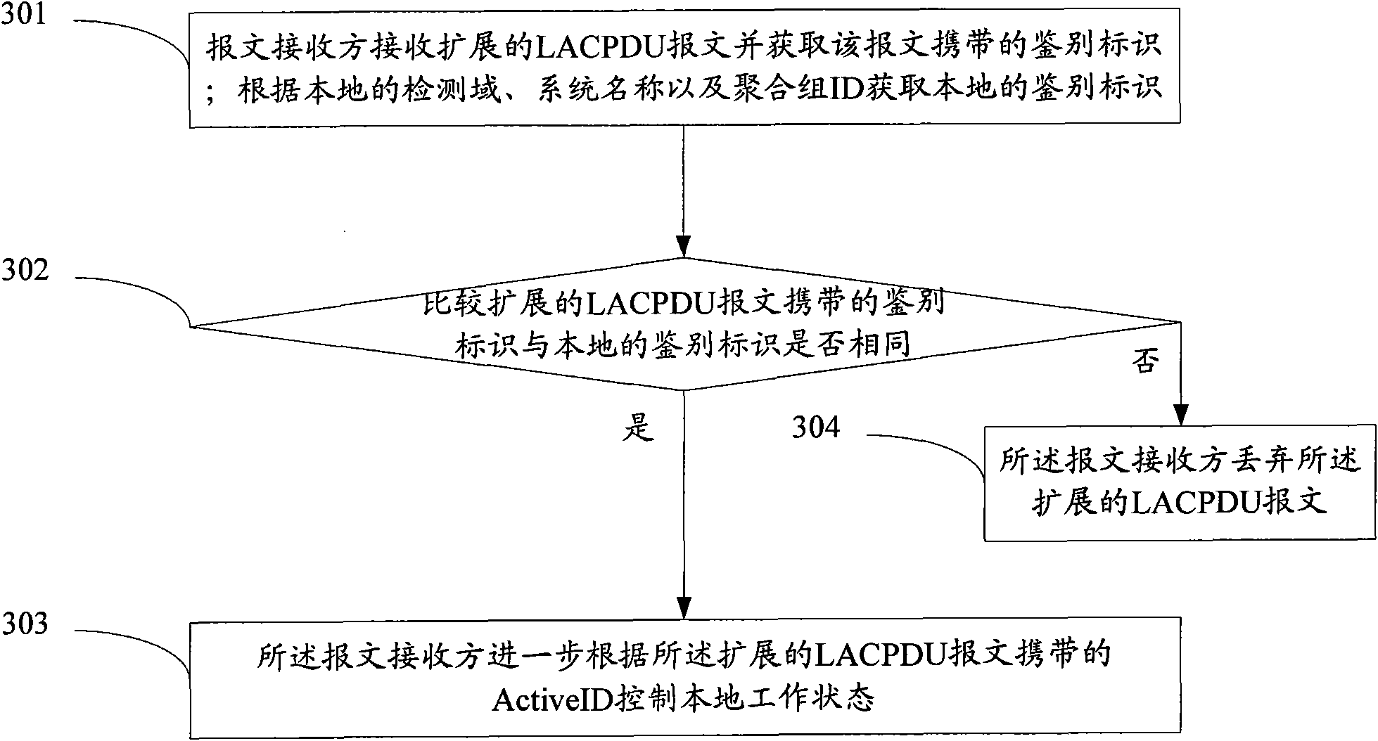
[0042] The present invention provides a method for LACPMAD detection, which is applied in a two-way stacking aggregation system, wherein an extended LACPDU message is used as a detection message for LACP MAD detection, and the extended LACPDU message carries a The authentication identifier of the stack attribution of the message sender and the ActiveID of the message sender, such as image 3 shown, including:

...


PUM


Abstract

The invention discloses an LACP MAD detection method. The method comprises the following steps: a message recipient obtains identity authentication carried by an expanded LACPDU message received, andobtains local identity authentication according to a local detection domain, a system name and an aggregation group ID; the message recipient compares whether the identity authentication carried by the expanded LACPDU message is the same as the local identity authentication; the message recipient further controls local working state according to Active ID carried by the expanded LACPDU message incase the comparison result is the same, and discards the expanded LACPDU message in case the comparison result is different. The method helps realize bidirectional stack LACP MAD detection by carryingthe identity authentication for distinguishing different stack systems in the expanded LACPDU message.

Description

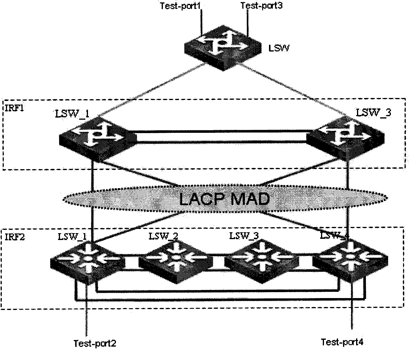
technical field [0001] The present invention relates to the communication field, in particular to a method and equipment for LACP MAD detection. Background technique [0002] In order to make the switch meet the port quantity requirements of the large-scale network, the stacking mode of the switch is generally adopted in the large-scale network to increase the port quantity. figure 1 Shown is a typical data center network diagram, in which the access layer is stacked by 4 LSW (LAN Switcher, local area network switch) low-end switch devices, the aggregation layer is stacked by 2 LSW mid-range switch devices, and the core layer is stacked by LSW A high-end switch device acts as a . The access layer is IRF2 (Intelligent Resilient Framework, Intelligent Resilient Framework), and the aggregation layer is IRF1. [0003] The access layer and the aggregation layer are connected through aggregated links, and multiple links are bundled to increase bandwidth and form a backup; for ex...

Claims


Application Information

Patent Timeline
Patent Type & Authority Applications(China)
IPC IPC(8): H04L12/26H04L12/56H04L47/41
Inventor 高平利
Owner NEW H3C TECH CO LTD
Learn More