
Method and device of control box

An operation method and control box technology, applied in the field of pipeline transmission system, can solve problems such as jamming and waste, and achieve the effect of reduced driving power and flexible operation

Active Publication Date: 2013-07-10
BEIJING RINRONG TECH
View PDF5 Cites 0 Cited by
  • Summary
  • Abstract
  • Description
  • Claims
  • Application Information

AI Technical Summary

Problems solved by technology

However, the existing control box is easy to get stuck when receiving the transmission cylinder, and requires a relatively large power to operate, resulting in waste

Method used


Image

  • Method and device of control box
  • Method and device of control box
  • Method and device of control box

Examples


example 1

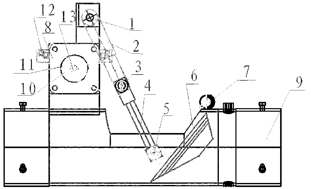
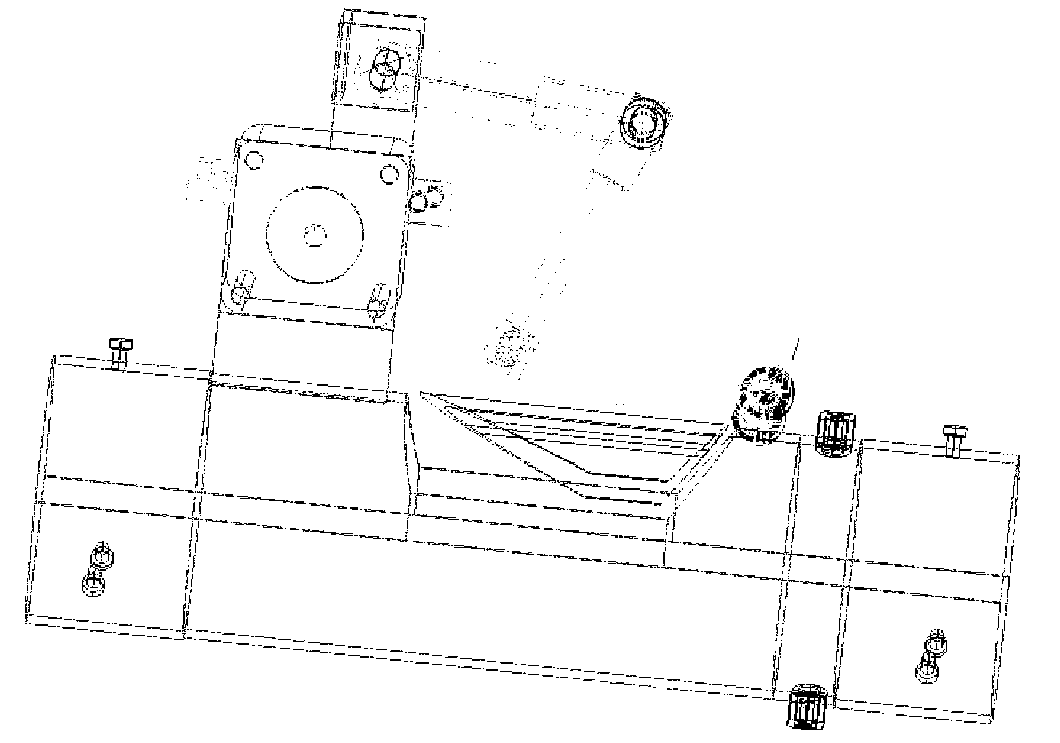
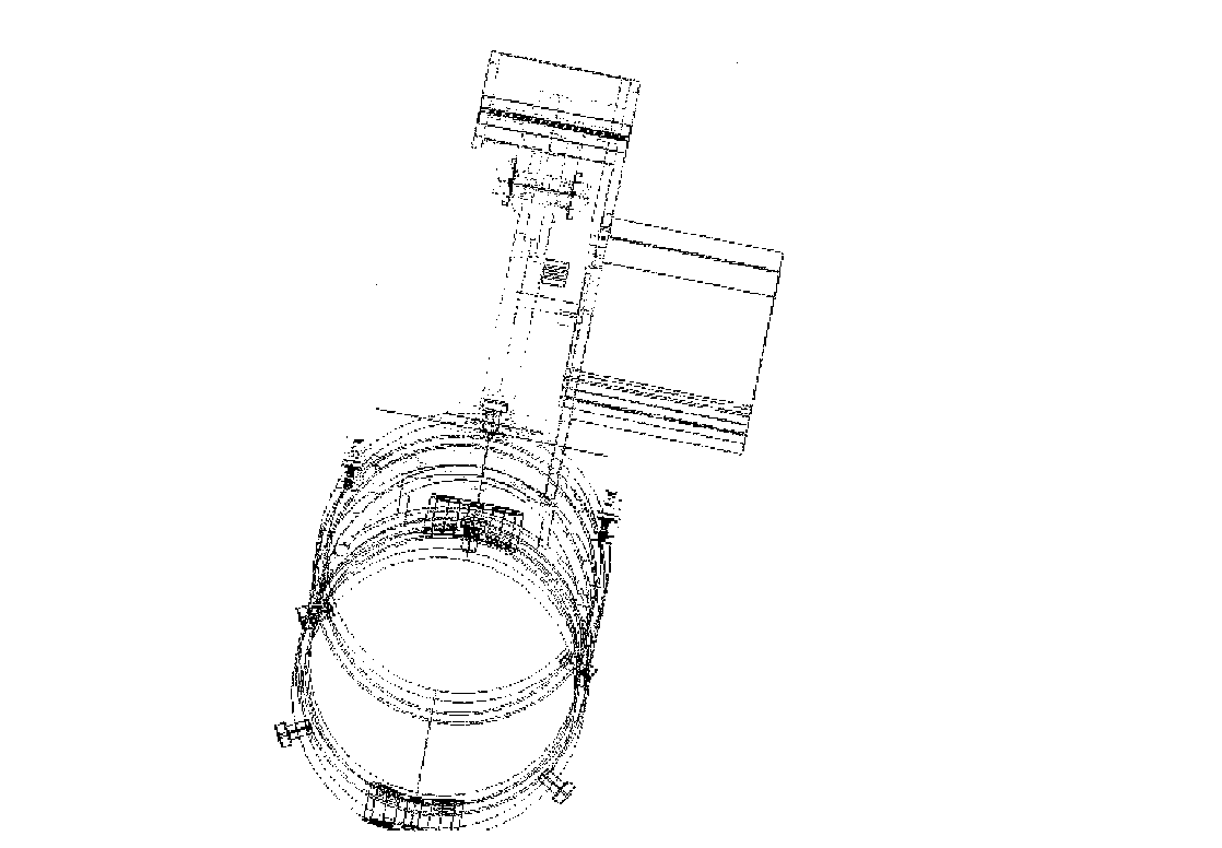
[0032] Such as figure 1 , 2 , 3, shown in 4, 9 is a pipe; 7 is an axle and an axle seat; 6 is a baffle plate; 4 baffle plate connecting rods; 10 is a motor crankshaft connecting rod 11 is a motor crankshaft; 1 is a fixed connecting rod shaft and a seat; 2 3 is the connecting shaft of the two rods; 4 is the movable connecting rod; 5 is the connecting shaft of 4 and 6; 13 is the motor;

[0033] Among them, the shaft is installed on the shaft seat, and the movement principle of the control box shows: when the motor crankshaft moves to the extreme position close to one end of the baffle, the motor crankshaft and the connecting rod of the motor crankshaft are located on a straight line, the baffle moves to the upper end, and the inner wall of the sliding slide of the baffle For the same curved surface, when the motor shaft rotates to the extreme position away from the end of the baffle, the motor crankshaft and the connecting rod of the motor crankshaft are on the same straight li...

example 2

[0036] Such as Figure 5 As shown, 15 is an electromagnet, 14 is a telescopic pull rod, 16 is a rotating shaft, and 17 is a rotating shaft bracket. When the electromagnet is powered on, the telescopic pull rod is pulled back, the two-bar mechanisms 2 and 4 are straightened, and the baffle is closed; when the electromagnet is powered off, the telescopic pull rod is ejected by the spring in the electromagnet, and the two-bar mechanisms 2 and 4 are bent , the shutter opens. Others are the same as example 1.


PUM


Abstract

The invention provides a method and a device of a control box, relating to the pipeline transmission system field. The pneumatic pipeline transmission system is a modern rapid logistics transmission tool, which can save time and improve work efficiency, however, the current control box is easy to be stuck when receiving a transmission barrel and needs a driving force with larger power to be operated again, thus causing waste. In order to solve the technical problem, the invention uses the following technical scheme: a driving device is arranged behind a baffle which is tightly sealed outside a channel in the process of receiving and under the closing state; the baffle can be opened by a small driving force under the pressure of a transmission carrier when receiving the transmission carrier; and the baffle can be locked in the state when being opened.

Description

technical field [0001] The invention relates to the field of pipeline transmission systems, in particular to an operation method and device for a control box. Background technique [0002] Pneumatic pipeline transmission system is a modern and fast logistics transportation tool. The pneumatic pipeline transmission system is used in hospitals, banks, office buildings, supermarkets, production workshops, laboratories and other places where a large number of items need to be transported every day. It can transmit medical records, medical certificates, medicines, laboratory tests, bills, cash, documents and any other items of appropriate size. The items are put into the transmission carrier during transmission, such as a special transmission cylinder, and the transmission cylinder ensures that the items are not damaged during the transmission process. The pneumatic pipeline transmission system transmits items from one workstation to another in the pipeline, which can not only ...

Claims


Application Information

Patent Timeline
Patent Type & Authority Patents(China)
IPC IPC(8): B65G51/26B65G51/04
Inventor 陆洪瑞
Owner BEIJING RINRONG TECH
Features
  • Generate Ideas
  • Intellectual Property
  • Life Sciences
  • Materials
  • Tech Scout
  • Unparalleled Data Quality
  • Higher Quality Content
  • 60% Fewer Hallucinations
Learn More