Ultraviolet acoustooptic device and optical imaging device

Inactive Publication Date: 2005-06-02
PANASONIC CORP
10 Cites 0 Cited by

AI-Extracted Technical Summary

Problems solved by technology

Furthermore, the acoustooptic device in which quartz glass, a quartz crystal, or a KDP crystal is used delivers poor acoustooptic performance, requires a large radio-frequency power source for driving the device, and has to be water-cooled to control the heat generated therein.
In the acoustooptic device in which the KDP crystal is used, it is difficult to have a moisture resistant structure since the KDP crystal is a water-soluble crystal.
Moreover, since the quartz crystal is a hard crystal, it takes a considerable time for processing it when it is used as an acoustooptic medium....

Method used

[0029] The present invention employs the aforementioned configurations and thereby can provide the following effects. [0030] (1) An acoustooptic device in which no laser damage nor optical damage is caused can be obtained by using an oxide crystal containing, particularly, boron as a component of its unit cell for the acoustooptic medium for ultraviolet light having a wavelength of 380 nm or shorter. [0031] (2) When an oxide crystal containing, particularly, a rare earth element and boron as components of its unit cell is used for the acoustooptic medium, an increased refractive index is obtained due to the effect of the rare earth element contained therein. Accordingly, considering the short absorption edge wavelength in the acoustooptic medium, high acoustooptic performance can be expected to be obtained. Furthermore, the rare earth element contained as a component of its unit cell allows the moisture resistance and mechanical strength to further improve as compared to the case of using a material containing only alkali metal or alkaline-earth metal, and boron as components of its unit cell. [0032] (3) A LN crystal or an oxide crystal containing boron as a component of its unit cell does not have the conventional disadvantages, such as high water-solubility of the KDP crystal and poor processability of the quartz crystal due to its considerable hardness. Accordingly, the oxide crystal is a medium that is practically easy to use. Consequently, an inexpensive ultraviolet acoustooptic device can be obtained. [0033] (4) When a Li2B4O7 crystal, a (GdY)1Ca4O(BO3)3 crystal, or a CsLiB6O10 crystal is used as the oxide crystal containing, particularly, boron as a component of its unit cell, a large crystal with a size of about 3 to 4 inches or 10 cm×10 cm can be utilized. This can keep the cost of the medium low. [0034] (5) By covering the acoustooptic medium with a thermal condu...

Benefits of technology

[0013] Hence, the present invention provides an acoustooptic device in which no laser damage nor optical damage is caused, and is intended to provide an ultraviolet acoust...

Abstract

The present invention provides an ultraviolet acoustooptic device including: a radio-frequency signal input part; a transducer unit for converting a radio-frequency signal into a mechanical vibration; and an acoustooptic medium whose optical characteristic varies according to the mechanical vibration. In the ultraviolet acoustooptic device, light entering the acoustooptic medium is ultraviolet light having a wavelength of 380 nm or shorter, and the acoustooptic medium is formed of an oxide single crystal containing at least boron as a component of its unit cell, a LiNbO3 crystal, or a LiNbO3 crystal doped with MgO. Thus, an acoustooptic device can be obtained in which no laser damage nor optical damage is caused, and an ultraviolet acoustooptic device and an optical imaging apparatus using the same can be provided that do not necessarily require to be water-cooled.

Application Domain

Non-linear optics

Technology Topic

Acousto-opticsSingle crystal +10

Image

  • Ultraviolet acoustooptic device and optical imaging device
  • Ultraviolet acoustooptic device and optical imaging device
  • Ultraviolet acoustooptic device and optical imaging device

Examples

  • Experimental program(5)

Example

Example 1
[0058] In order to examine laser damage and optical damage caused by ultraviolet light, various kinds of single crystal materials were evaluated with respect to their light resistance using a laser having a light source of third harmonics of a YAG laser. The result is shown in Table 1. The crystal materials evaluated herein were a TeO2 crystal that had been used conventionally, and LN, MgO:LN, Li2B4O7, (GdY)1Ca4O(BO3)3, and CsLiB6O10 that were used for the acoustooptic device of the present invention. TABLE 1 Absolute Value Presence or of Laser Damage Relative Value Absence of Threshold of Laser Damage Optical Material (kW/mm2) Threshold Damage TeO2 29 1 Absent LN 87 3 Present MgO:LN 57-87 2-3 Absent Li2B4O7 At least 120 At least 4 Absent (GdY)1Ga4O(BO3)3 At least 120 At least 4 Absent CsLiB6O10 At least 120 At least 4 Absent
[0059] From the result, it is understood that among these materials, the TeO2 crystal has the lowest relative value of the laser damage threshold and therefore is the most susceptible to the laser damage. In this case, the “laser damage” denotes the state where the crystal surface was damaged by a laser beam and a concave portion was formed at the surface. Particularly, in the case of using TeO2, a metal Te was observed when the concave portion and its surrounding portion were analyzed using an X-ray microanalyzer. This conceivably is because of cleavage of chemical bonds caused by absorption of strong ultraviolet light and heat. Consequently, the TeO2 crystal is not suitable for the use in which high power is used. LN and MgO:LN showed the laser damage thresholds that are about twice to triple as high as that of TeO2. Regarding MgO:LN, the amount of MgO used therein was preferably in the range of 0.5 to 7 mol. %, and an acoustooptic medium made of MgO:LN containing more than 7 mol. % of MgO as a dopant was considerably susceptible to laser damage. In the Li2B4O7 crystal, the (GdY)1Ca4O(BO3)3 crystal, and the CsLiB6O10 crystal, the laser damage threshold was at least four times as high as that of the TeO2 crystal, and no damage was measured in this evaluation.
[0060] The above-mentioned results showed that LN, MgO:LN, and oxide single crystals containing boron as the main component have higher damage thresholds than that of the TeO2 crystal that has been used conventionally.
[0061] Next, the acoustooptic media made of the above-mentioned materials were evaluated with respect to the optical damage. The evaluation was carried out under the conditions that an argon laser was used as a light source, and the laser intensity at the sample position was 1.8 kW/mm2. As is known conventionally, optical damage (the distortion in a beam pattern) was found in the acoustooptic medium made of the LN crystal that was not doped with MgO. No optical damage, however, was found under the same conditions in the acoustooptic media made of the TeO2 crystal, the MgO:LN crystal, the Li2B4O7 crystal, the (GdY)1Ca4O(BO3)3 crystal, and the CsLiB6O10 crystal. As the result of the optical damage, the laser beam pattern was deformed considerably into an ellipse or was not uniform.
[0062] As described above, among LN crystals, particularly a LN crystal doped with MgO is subjected to less optical damage. Hence, a LN crystal doped with 0.5 to 7 mol. % of MgO that is subjected to less optical damage as well as less laser damage conceivably is suitable for the acoustooptic medium. Since no optical damage was found in the Li2B4O7 crystal, the (GdY)1Ca4O(BO3)3 crystal, and the CsLiB6O10 crystal, they are considered to be adaptable to both the case where peak power is high and the case where continuous light is used.
[0063] Next, ultraviolet acoustooptic devices like the one shown in FIG. 1 were produced using various acoustooptic media, and the acoustooptic effects of the various acoustooptic media were checked. In this case, the acoustooptic performance is not always reflected as it is since the acoustic impedances of the transducer unit 2 and the acoustooptic medium 3 and the electrical impedances of the radio-frequency signal generator and the transducer unit 2 were not optimized. However, when using third harmonics of a pulsed NdYAG laser with a wavelength of 355 nm that was employed as a light source, the diffraction efficiency was about 5% to 20% as shown in Table 2, with the power of incoming radio-frequency signals being 2 to 3 W. Furthermore, in this case, the acoustooptic devices did not require to be water-cooled or the like.
[0064] Particularly, by covering the acoustooptic media with a thermal conductive sheet, it was possible to obtain ultraviolet acoustooptic devices in which no defocus nor drift of laser beams occurs. In this connection, a graphite sheet was particularly useful as the thermal conductive sheet since it had a thermal conductivity that was twice that of copper. TABLE 2 Diffraction Material Efficiency (%) LN 20 MgO:LN 20 Li2B4O7 5 (GdY)1Ga4O(BO3)3 6 CsLiB6O10 5
[0065] It is to be understood that an impedance matching circuit may be provided between the radio-frequency signal generator and the transducer unit 2, although it was not used here.

Example

Example 2
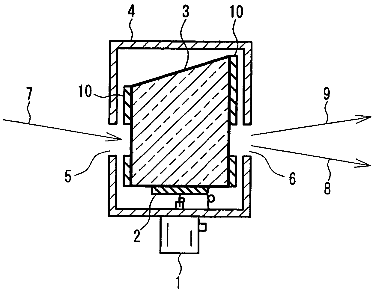
[0066] Acoustooptic devices like the one shown in FIG. 1 were produced and their acoustooptic performance was evaluated as in Example 1 using a GaN-based LED that emitted light having a wavelength in the range of 360 nm to 380 nm. The LED used herein had a maximum output of about 2 mW.
[0067] In this case, the diffraction efficiency was about 4% to 15% as shown in Table 3, with the input power of an RF signal being 2 W. The reason why the diffraction efficiency decreased as compared to that in Example 1 conceivably is that the wavelength of the incident light was slightly longer and the monochromaticity of the light source was poorer. When using the incident light having power in this range, no optical damage was found even in the case of using a common LN single crystal. TABLE 3 Diffraction Material Efficiency (%) LN 15 MgO:LN 15 Li2B4O7 4 (GdY)1Ga4O(BO3)3 5 CsLiB6O10 4

Example

Example 3
[0068] Acoustooptic devices like the one shown in FIG. 1 were produced and their acoustooptic performance was evaluated with respect to fourth harmonics of a YAG laser having a wavelength of 266 nm. In this case, it was not possible to use LN and MgO:LN for the acoustooptic devices since they do not transmit ultraviolet light having a wavelength of 266 nm. The diffraction efficiency of the acoustooptic devices produced using the Li2B4O7 crystal, the (GdY)1Ca4O(BO3)3 crystal, and the CsLiB6O10 crystal was 6% to 8% as shown in Table 4. In addition, deteriorations in transmittance and beam pattern were not found even after these acoustooptic devices were irradiated with ultraviolet light having a wavelength of 266 nm for 10 hours continuously. TABLE 4 Diffraction Material Efficiency (%) LN — MgO:LN — Li2B4O7 6 (GdY)1Ga4O(BO3)3 8 CsLiB6O10 7
[0069] With respect to the (GdY)1Ca4O(BO3)3 crystal, in the case of using light having a wavelength of 266 nm, higher light transmittance was obtained when YCa4O(BO3)3 in which light absorption by Gd is reduced or a composition hardly containing Gd was used.

PUM

no PUM

Description & Claims & Application Information

We can also present the details of the Description, Claims and Application information to help users get a comprehensive understanding of the technical details of the patent, such as background art, summary of invention, brief description of drawings, description of embodiments, and other original content. On the other hand, users can also determine the specific scope of protection of the technology through the list of claims; as well as understand the changes in the life cycle of the technology with the presentation of the patent timeline. Login to view more.
Why Eureka
Try Eureka