Wire rod protection chain

A technology of chains and wires, applied in the field of load-bearing structures, can solve the problems that the box cannot be pushed into the casing, the way and position of the wires cannot be folded as expected, and the wires are entangled.

Inactive Publication Date: 2010-03-24
INVENTEC CORP
View PDF0 Cites 4 Cited by
  • Summary
  • Abstract
  • Description
  • Claims
  • Application Information

AI Technical Summary

Problems solved by technology

Due to the long length of the wires, when the box is pushed into the case, the way and position of the wires cannot be folded as expected, and somet...

Method used


Image

  • Wire rod protection chain
  • Wire rod protection chain
  • Wire rod protection chain

Examples


Embodiment Construction

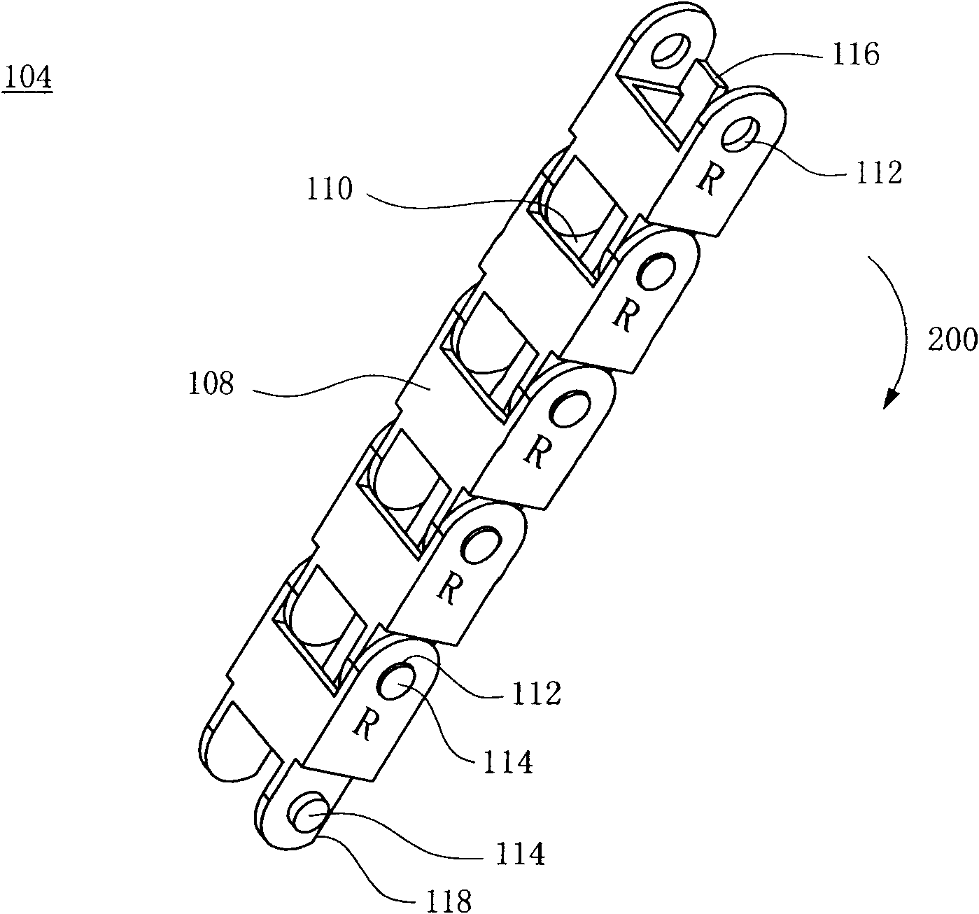
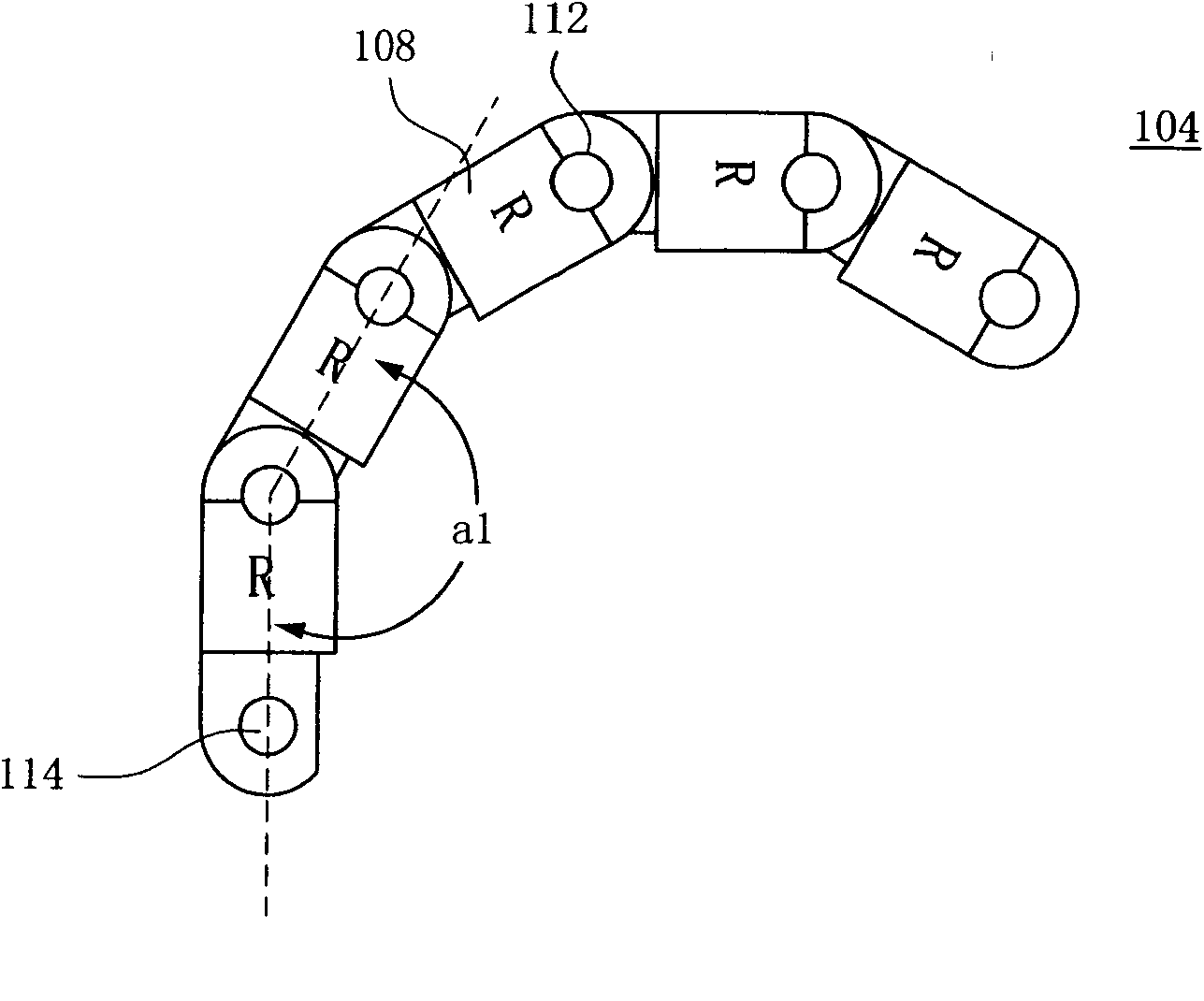
[0032] Please also refer to Figure 1A and Figure 1B . Figure 1A and Figure 1B A perspective view and a side view, respectively, of the forward segment 104 of the embodiment of the present invention. The forward segment 104 is basically formed by linking a plurality of forward chain units 108 . Please note that there are many types of the forward chain unit 108, and the linking methods are also different. Although a type of the forward chain unit 108 is provided for illustration, the type of the forward chain unit 108 is not limited.

[0033] In the embodiment of the present invention, each forward chain unit 108 has a through hole 110 , and two openings of the through hole 110 are respectively provided with a hole 112 and a shaft 114 , and the size and position of the hole 112 are matched with the shaft 114 To socket shaft 114 . By fitting the hole 112 of one forward chain unit 108 to the shaft 114 of the other forward chain unit 108, the two forward chain units 108 ar...


PUM

PropertyMeasurementUnit
Angleaaaaaaaaaa
Angleaaaaaaaaaa

Abstract

The invention relates to a wire rod protection chain comprising forward sections and reverse sections which are staggered and interlinked. In the invention, each forward section is provided with a plurality of forward chain single bodies which are interlinked, wherein every two interlinked forward chain single bodies form an included angle limited within 0-180 degrees; and each reverse section isprovided with a plurality of reverse chain single bodies which are interlinked, wherein every two interlinked reverse chain single bodies form an included angle limited within 180-360 degrees, so thatthe wire rod protection chain can be folded in a zigzag manner.

Description

technical field [0001] The present invention relates to a bearing structure of an electronic device, and in particular, to a device for protecting and storing electric wires. Background technique [0002] Generally speaking, a large-scale machine is usually loaded with multiple electronic devices such as hard disks, optical drives, processors or fans. In order to facilitate assembly, a connector is usually installed on the installation position of the machine, and the connector is electrically connected to the power supply. After the electronic device is connected to the connector, power can be obtained. On the other hand, the electronic device can also be electrically connected to the circuit board in the machine through the connector. [0003] At present, most of the common machines adopt a hot-plug design structure, which means that the connection between the connector and the power supply adopts a design that can be repeatedly pulled and inserted. Taking a rack-type se...

Claims


Application Information

Patent Timeline
IPC IPC(8): H02G11/00H05K7/02F16G13/16
Inventor 徐永清陈伟仕杨棨錞
Owner INVENTEC CORP
Why Eureka
Try Eureka