Device for positioning a stent

A device, the technology of the guide, used in the field of urology

Active Publication Date: 2010-03-24
马里昂·德沃纳
View PDF4 Cites 15 Cited by
  • Summary
  • Abstract
  • Description
  • Claims
  • Application Information

AI Technical Summary

Problems solved by technology

[0015] These three examples do not really reproduce the correct positioning of the stent on either side of the striated sphincter, i.e., the upper tube is in the prostatic urethra, its tip is in the bladder, and the lower tube is in the bulbous urethra with the flexibly connected by sphincter

Method used


Image

  • Device for positioning a stent
  • Device for positioning a stent
  • Device for positioning a stent

Examples


Embodiment Construction

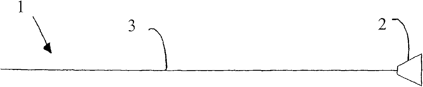
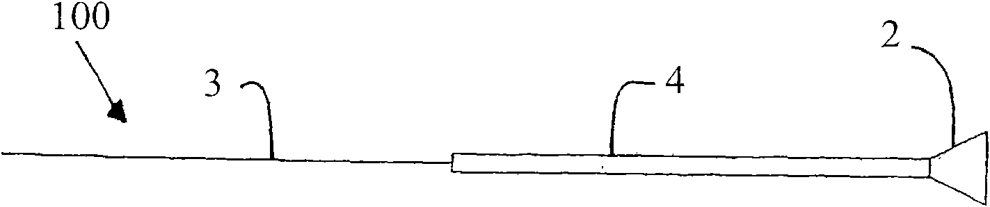
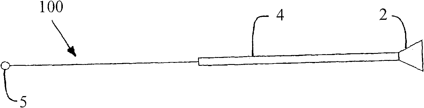
[0069] like Figures 1a-1d As shown, the guide 1, 100 includes at least one flexible portion having longitudinal rigidity and lateral flexibility. The guide 1 , 100 includes a proximal end with an abutment mechanism 2 . The abutment means 2 may have a substantially conical shape extension, which may be hollow or solid. In fact, as Figure 3a and Figure 3b As shown, the guide 100 is inserted into the push tube 16 such that the abutment mechanism 2 of the guide 100 is in contact with the proximal end 17 of the push tube 16 , which may have a complementary shape to the abutment mechanism 2 .

[0070] The length of the guide 1 , 100 is chosen to correspond to the length of the stent 6 plus the length of the obstacle, which may be the sphincter 21 , plus the length of the push tube 16 .

[0071] The longitudinal rigidity of the guide 1 , 100 makes the distal end of the guide 1 , 100 rigid enough to push the blind end of the stent 6 forward through the lumen of the natural cond...


PUM


Abstract

The invention concerns a device (23) for positioning a stent in a natural canal (22) after the passage through an obstacle at the level of a target organ (19). The device (23) comprises a stent (6), a pusher tube (16) and a guide (1). The said guide (1) is conceived to push the stent (6) through the lumen of the natural canal (22), and comprises at least one flexible part having a predetermined longitudinal stiffness and a lateral flexibility consisting in a reversible deformation from a straight position to a bent position so as to follow the curve of the natural canal (22) under the application of minimal external forces exerted by an operator. The invention is particularly adapted to the technical field of urology.

Description

technical field [0001] The present invention relates to an apparatus for positioning a stent in a natural conduit at the target organ level after passing through an obstacle, which may be a sphincter muscle. [0002] The present invention is particularly suitable for the technical field of urology, where an endourethral stent has to be inserted into the bladder after passing along the male urethra through the striated urethral sphincter in order to inhibit obstruction in the area of ​​the prostatic urethra and allow urine to flow from the bladder Fluid flows through at least one orifice positioned laterally at the distal end of the stent. [0003] However, it is clear that the device according to the invention can be used to allow insertion of a stent into the lumen of the natural conduit of another target organ. Background technique [0004] Insertion of the stent into the lumen of the natural conduit must be performed carefully without causing any damage by passing throug...

Claims


Application Information

Patent Timeline
Patent Type & Authority Applications(China)
IPC IPC(8): A61F2/04A61M31/00A61M25/00A61F2/84A61M25/04A61F2/94
CPCA61F2/95A61F2/94A61F2002/048A61F2/04A61F2002/047
Inventor 马里昂·德沃纳
Owner 马里昂·德沃纳
Why Eureka
Try Eureka