Implant for influencing blood flow

An implant and blood flow technology, applied in the field of vascular implants, can solve problems such as stent deformation, and achieve the effect of firm connection and no trauma

Active Publication Date: 2010-03-24
PHENOX
View PDF2 Cites 18 Cited by
  • Summary
  • Abstract
  • Description
  • Claims
  • Application Information

AI Technical Summary

Problems solved by technology

However, U-shaped links tend to cause stress and thus deformation of the stent

Method used


Image

  • Implant for influencing blood flow
  • Implant for influencing blood flow
  • Implant for influencing blood flow

Examples


Embodiment Construction

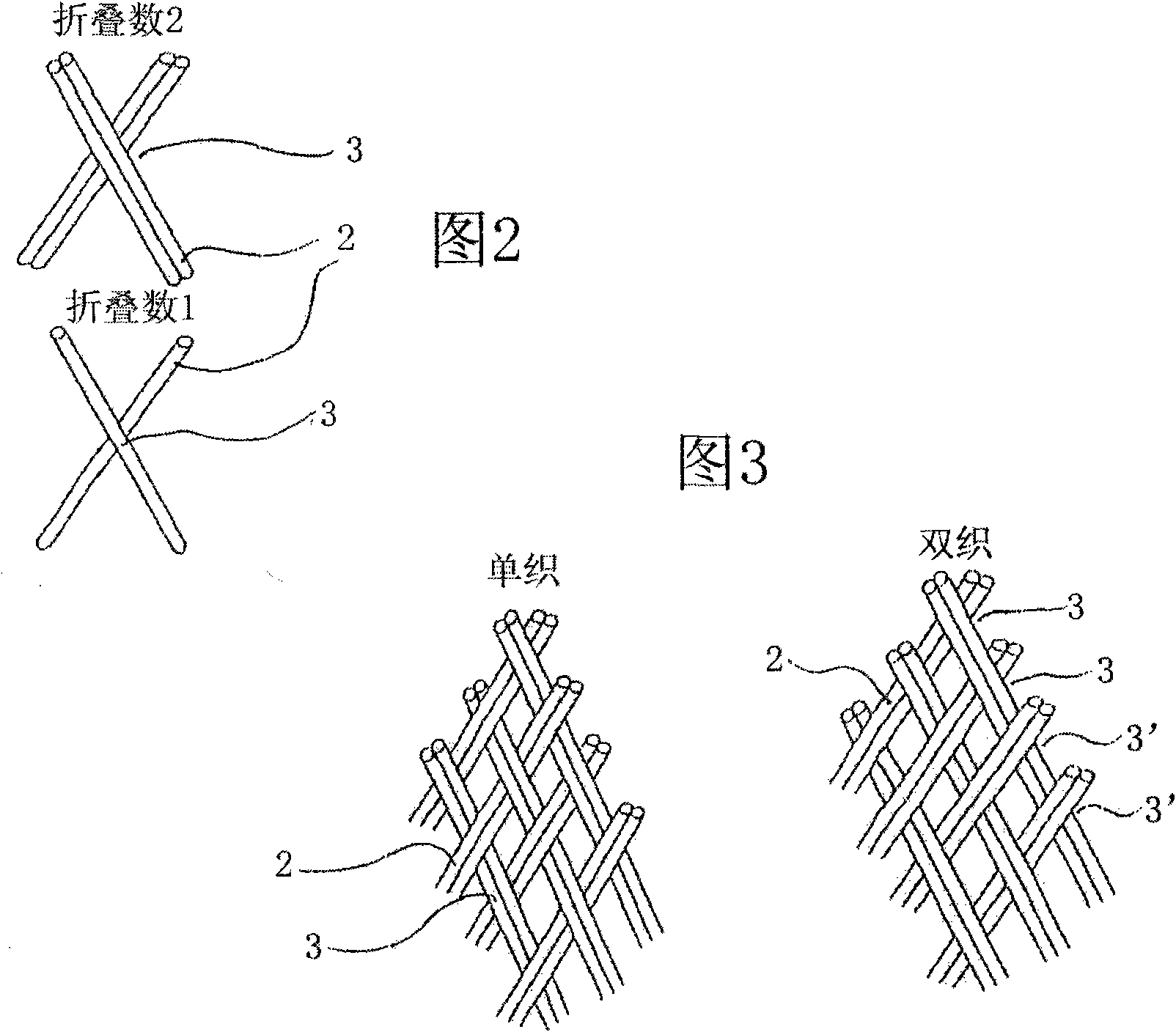
[0058] figure 1 The braided structure of the implant 1 of the invention is shown consisting of individual filaments 2 entangled with each other. In the example shown the individual filaments intersect at an angle of approximately 120° with the flared side of the angle pointing towards the open end of the circular braid. The illustration shows the braid in a slightly stretched / elongated state, ie the diameter is reduced.

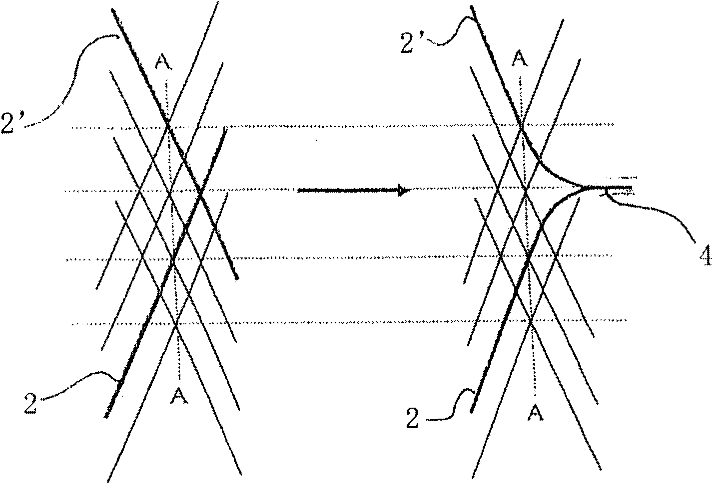
[0059] The angle Θ represents the braid angle relative to the longitudinal axis, which can be as high as 80 degrees in the unstretched condition and when the nominal diameter is reached. The angle Θ can be reduced to about 7 degrees when the braid is in the extended position inside the catheter.

[0060] It should be understood that the nominal diameter of the circular braid will match the lumen of the target vessel at the site to be treated.

[0061] Braids are produced in endless braided structures on conventional braiding machines. Braiding takes place...


PUM


Abstract

The invention relates to an implant for blood vessels, in particular for influencing the blood flow in the region of arteriovenous malformations, having a wall made of individual filaments combined toform a braided edge, said braided edge in an insertion catheter takes on an elongated shape having a reduced diameter and at the implant site expands while adapting to the vessel diameter and increasing the braiding density.

Description

technical field [0001] The present invention relates to implants for blood vessels having a wall comprising individual filaments combined to form a circular implant. The implant will be particularly useful in affecting blood flow in areas of arteriovenous malformations such as fistulas and aneurysms. It can also be used eg in the treatment of ischemic stroke to restore, increase or maintain blood flow. The implant can be designed to be recoverable. Background technique [0002] Arteriovenous malformations can significantly harm the patient and can even be fatal. In particular, this applies to arteriovenous fistulas and aneurysms, especially when these are found to be present in brain regions. Typically, attempts are made to isolate such deformities by implants, which are usually placed in place by endovascular techniques with the aid of a catheter. [0003] Especially when treating aneurysms the implantation of a platinum helix, which more or less completely fills the an...

Claims


Application Information

Patent Timeline
Patent Type & Authority Applications(China)
IPC IPC(8): A61F2/90A61F2/82A61F2/95
CPCA61F2250/0039A61F2/90A61F2002/823A61F2002/9505A61F2250/0015D04C1/06D10B2509/06
Inventor R·汉内斯H·蒙斯塔特曼纽尔·施奈德
Owner PHENOX
Why Eureka
Try Eureka