
Dynamic reciprocating-bob rheometry

一种流变特性、驱动电流的技术,应用在测量装置、流动特性、取样等方向,能够解决阻碍研究人员筛选等问题

Active Publication Date: 2010-03-24
PETROLEUM ANALYZERS LLC
View PDF1 Cites 1 Cited by
  • Summary
  • Abstract
  • Description
  • Claims
  • Application Information

AI Technical Summary

Problems solved by technology

The cost of some of these fluids tends to discourage researchers from screening them

Method used


Image

  • Dynamic reciprocating-bob rheometry
  • Dynamic reciprocating-bob rheometry
  • Dynamic reciprocating-bob rheometry

Examples


Embodiment Construction

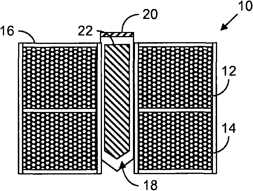
[0021] figure 1 is a cross-sectional view of one type of sensor that can employ the teachings of the present invention. The sensor 10 is generally cylindrical and includes two respectively driven coils 12 and 14 which are axially displaced from each other and communicate through a housing 16 with the liquid whose viscosity or other property is to be measured. isolation. Fluid is however allowed to flow into a central sample well 18 , at the inlet of which a pendulum retaining bracket 20 is provided which confines a ferromagnetic pendulum 22 to the well 18 . Driving the two coils 12 and 14 alternately causes the pendulum 22 to reciprocate against the viscous resistance of the sample liquid.

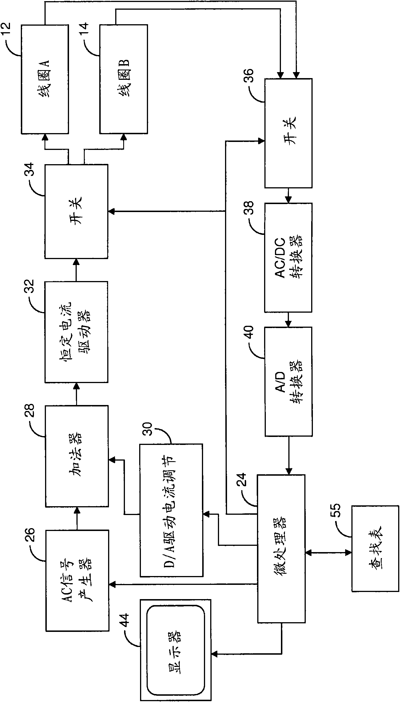
[0022] figure 2 The control circuit used to obtain this result is depicted. Microprocessor 24 controls AC signal generator 26 to generate an AC signal which summing circuit 28 adds to a DC signal from microprocessor controlled digital-to-analog converter 30 . The resulting output of ...


PUM


Abstract

A sensor for making rheological measurements takes the form of a ferromagnetic bob alternately driven through a sample fluid in opposite directions by magnetic force from two alternately driven coils. The bob's position affects the mutual inductance between the coils, so it can be inferred by sensing the signal that current flowing in one coil induces in the other, and rheological properties are determined from the relationships among the bob's motion, the coil current, and the sensor geometry. Some such measurements' accuracies are enhanced by computing bob acceleration and suppressing iner-tial effects thereby detected.

Description

[0001] priority claim [0002] This application claims priority to the following patent application: U.S.S.N. 11 / 691554, the entire content of which patent application is hereby expressly incorporated by reference. technical field [0003] The present invention relates to the measurement of viscosity and related fluid properties. It has particular application in the use of sensors employing reciprocating magnetically driven bobs. Background technique [0004] The rheological properties of fluids have been the object of study for more than a century, and nearly as long have been routinely measured in laboratories to characterize fluids recently developed or encountered. Apparatus for this purpose typically employ rotating cylindrical elements to subject the fluid of interest to shear, and various rheological properties are inferred from the fluid's resistance to this shear at various cylinder velocities. Examples of properties determined by such a device are whether the ...

Claims


Application Information

Patent Timeline
Patent Type & Authority Applications(China)
IPC IPC(8): G01N1/00G01N11/12
CPCG01N11/10
Inventor D·A·艾里J·T·科尔
Owner PETROLEUM ANALYZERS LLC
Learn More