Circuit breaker with switching gas cooling

A technology of circuit breakers and casings, applied in the field of circuit breakers, can solve problems such as the influence of circuit breaker manufacturing prices

Inactive Publication Date: 2010-03-24
SIEMENS AG
View PDF1 Cites 13 Cited by
  • Summary
  • Abstract
  • Description
  • Claims
  • Application Information

AI Technical Summary

Problems solved by technology

The disadvantage of the previously described embodiment for cooling gas is that many different components have to be produced and installed in the circuit breaker
The cost of manufacturing and assembling these components adversely affects the manufacturing price of the circuit breaker

Method used


Image

  • Circuit breaker with switching gas cooling
  • Circuit breaker with switching gas cooling
  • Circuit breaker with switching gas cooling

Examples


Embodiment Construction

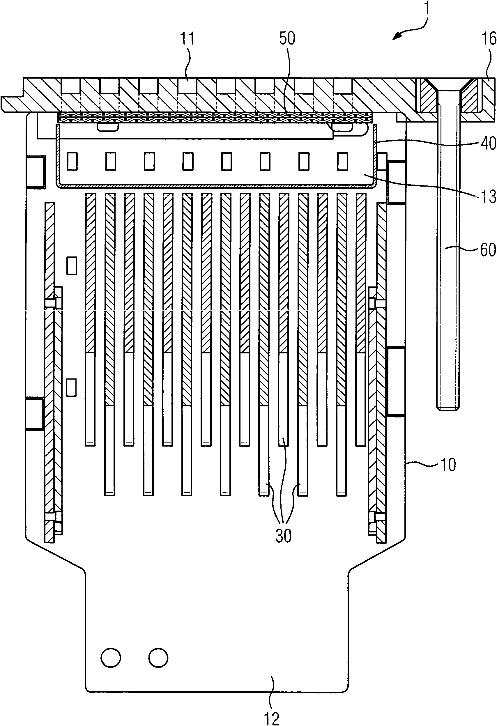
[0031] about in figure 1 and figure 2 The conventional circuit breaker shown in has been described with reference to the prior art.

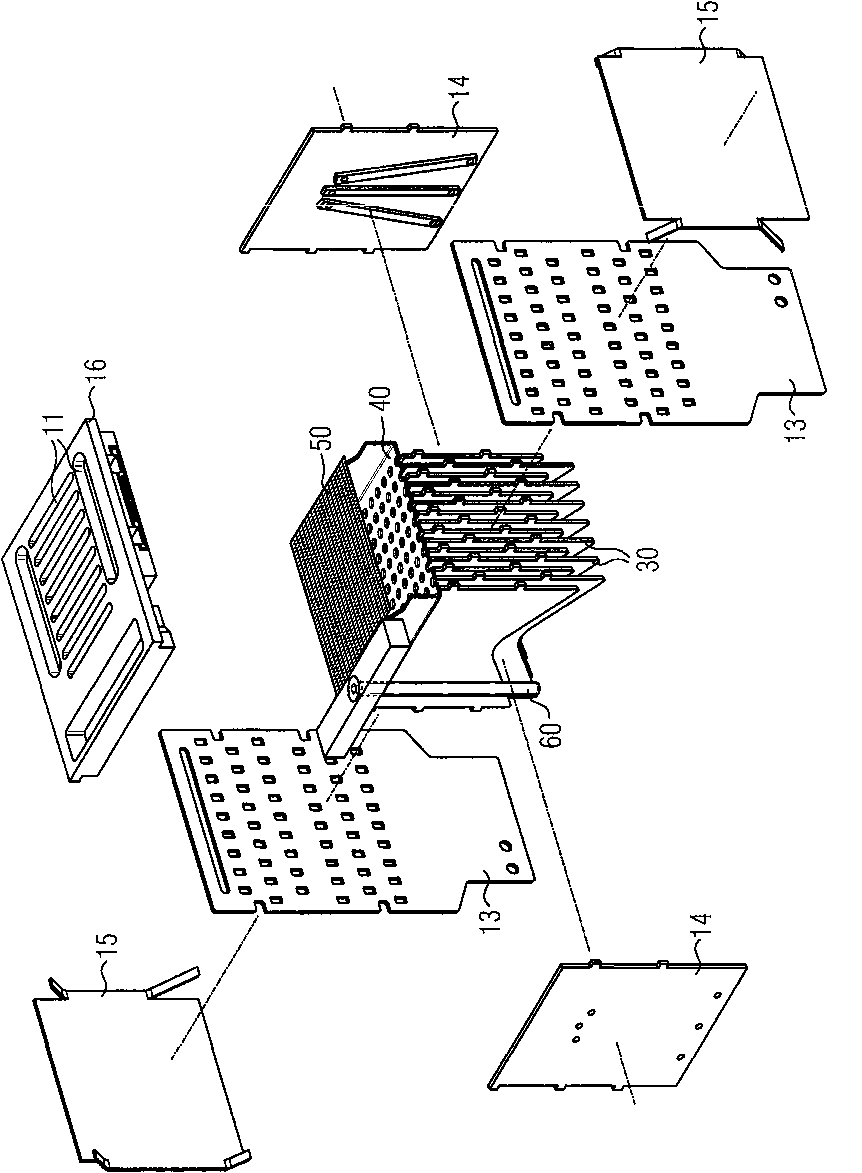
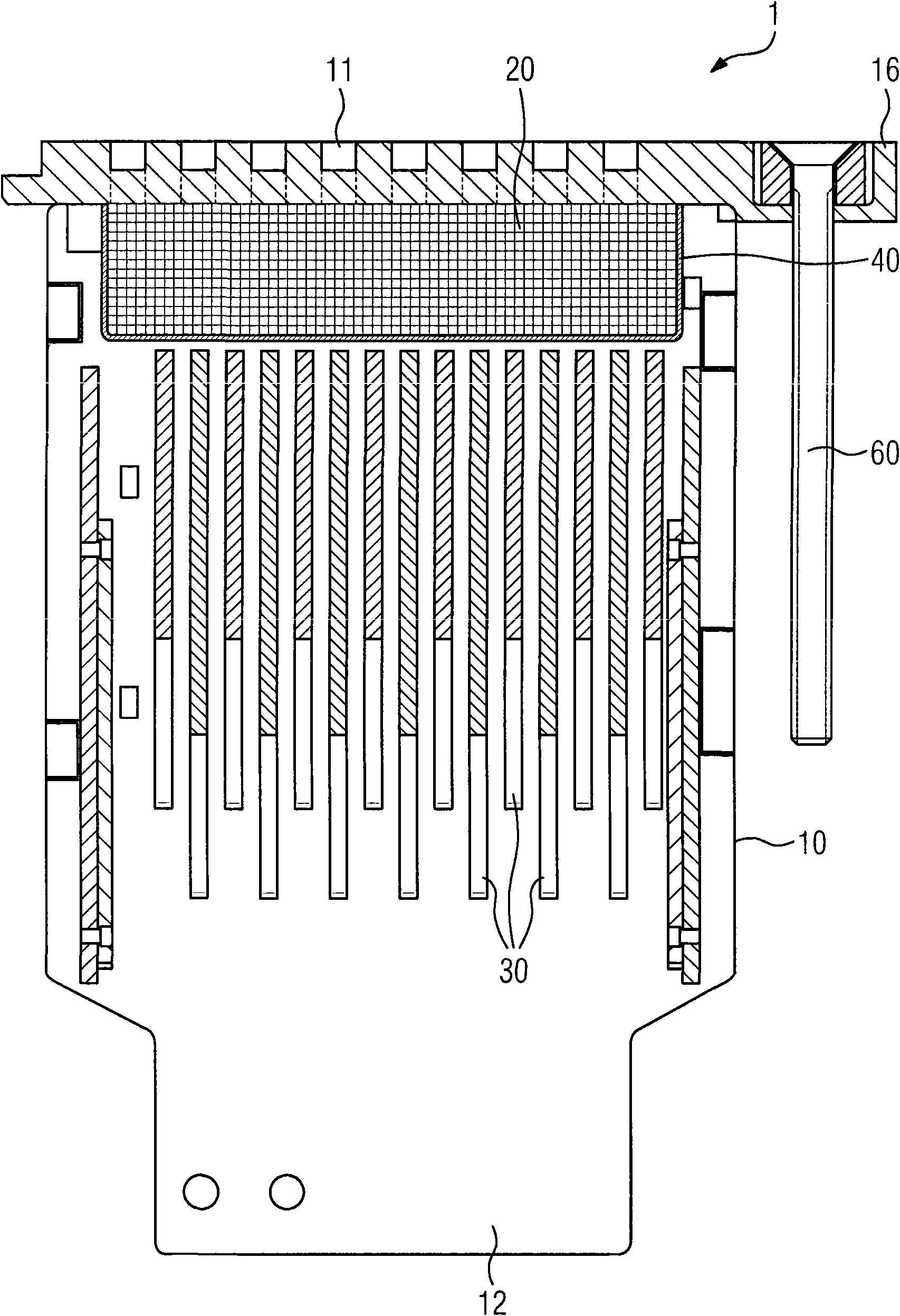
[0032] exist image 3 In the embodiment shown in , the external dimensions of the circuit breaker 1 according to the present invention are basically defined by the housing 10 and the top cover 16 fixed thereon, wherein the top cover 16 can be regarded as the housing constituting the surface of the circuit breaker a part of. The entire housing 10 is fastened via the cover 16 by means of fastening screws 60 , for example in the distribution system.

[0033] A switching chamber 12 is formed in the housing 10 of the circuit breaker 1 , in which the contacts (not shown) of the circuit breaker 1 which are movable relative to each other are arranged. Arranged parallel to one another above the switching chamber 12 are a plurality of arc extinguishing plates 30 which serve to reduce the arc that occurs between the contacts when the contacts are ope...


PUM


Abstract

The invention relates to a circuit breaker comprising at least one housing having at least one opening, and at least one pair of contacts located in the housing, the contacts of the pair of contacts being mobile in relation to each other for opening and closing an electric circuit. The invention is characterized in that an open-pore metal foam (20) is interposed between at least one of the pairs of contacts and at least one housing opening (11), the metal foam being electrically insulated from the current-carrying elements of the circuit breaker (1). The invention further relates to the use ofan open-pore metal foam (20), produced of a zinc base alloy or aluminum base alloy, as a cooling structure for the dissipation of heat from switching gases that are produced by an electric switchingprocess.

Description

technical field [0001] The invention relates to a circuit breaker having a housing with at least one opening and at least one contact pair arranged in the housing, wherein the contacts of the contact pair can be moved relative to each other for opening and closing an electrical circuit. Background technique [0002] Electromechanical distribution devices placed in the grid for the purpose of distributing electricity limit or disconnect the current in the grid. In order to limit the current, the metal contacts arranged as contact pairs are separated from one another, wherein an arc is generated between the two contacts, which arc has an ignition voltage in the capacity stage of the drive voltage in the network. The melting of the surface particles by the contact surface produces a thermally ionized gas which expands due to the temperature increase and thus heats the adjacent gas layer and the surface together. There is a risk of damage to the switch housing due to the expans...

Claims


Application Information

Patent Timeline
Patent Type & Authority Applications(China)
IPC IPC(8): H01H9/34
CPCH01H9/342H01H9/345Y10T29/49105Y10T29/49826
Inventor 维尔纳·哈特曼米夏埃尔·巴赫德特勒夫·施密特京特·赛德勒赛扎伊·蒂尔克曼阿图尔·魏因贝格
Owner SIEMENS AG
Why Eureka
Try Eureka