Method for constructing bottom of ladle

A manufacturing method and technology of molten steel tanks, which are applied in the direction of manufacturing tools, casting molten material containers, metal processing equipment, etc., can solve the problems of increasing costs and delaying production, and achieve the effect of reducing labor intensity and reducing operating costs

Active Publication Date: 2012-07-18
ANGANG STEEL CO LTD
View PDF0 Cites 0 Cited by
  • Summary
  • Abstract
  • Description
  • Claims
  • Application Information

AI Technical Summary

Problems solved by technology

It not only increases the cost,

Method used


Image

  • Method for constructing bottom of ladle
  • Method for constructing bottom of ladle
  • Method for constructing bottom of ladle

Examples


Embodiment Construction

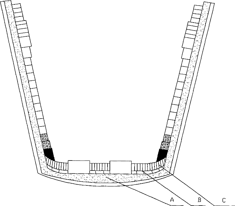
[0019] See figure 1 , a method for manufacturing the bottom of a steel ladle, the method comprising the steps of:

[0020] (1) Make the permanent bottom A of the molten steel tank into a concave permanent bottom, and use a concave mold to make it; put the concave mold into the bottom of the tank smoothly, so that the distance between the edge of the mold and the wall of the molten steel tank is balanced, and protect the air-permeable square brick Sleeve, nozzle brick protection sleeve is aligned with ventilating brick mouth and nozzle brick mouth;

[0021] (2) The stirred permanent bottom castable is poured into the bottom of the tank from the gap between the mold and the tank wall until the upper surface of the castable touches the lower surface of the mold. till pulp;

[0022] (3) Hang out the mold after the castable is solidified;

[0023] (4) Carry out health maintenance for the permanent bottom, and the health maintenance should not be less than 24 hours;

[0024] (5)...


PUM


Abstract

The invention relates to a method for constructing a concave bottom of a ladle. A concave mould is adopted for constructing the bottom of the ladle, during construction, the concave mould is firstly placed at the bottom of the ladle, and distances between the edges of the concave mould and the walls of the ladle are equal; then stirred castables are poured into the bottom of the ladle from a seambetween the concave mould and the wall of the ladle, and the concave mould is lifted up after the castables are solidified; and finally a brick body is constructed on the surface of the castables. The method is used for constructing the bottom of the ladle so that the brick body constructed on the surface of the castables cannot be jacked up under the condition of heating, thereby simplifying theprocess of making up the seam, saving the production cost and lightening the working intensity of operators.

Description

technical field [0001] The invention relates to a masonry method for a concave tank bottom of a molten steel tank Background technique [0002] The original masonry method of the bottom of the steel ladle tank is permanent bottom horizontal ramming. After the installation of ventilating square bricks and nozzle square bricks is completed, ramming materials are put into the bottom of the tank and smoothed manually, so that the permanent bottom is horizontal. After the permanent bottom is solidified, vertical bricks are laid on it, and the breathable upper and lower bricks are directly built on the base of the bottom. After the ladle is baked, the brick at the bottom of the package is heated and expanded. The bottom of the tank expands and jacks up, which lifts up the square bricks and creates gaps between the upper and lower bricks. If the gap is less than 5mm, it is often filled up by workers applying magnesium ash; if the gap is as large as 5-20mm, it can no longer be mad...

Claims


Application Information

Patent Timeline
IPC IPC(8): B22D41/00B22D41/02
Inventor 刘伟王斌刘文东武学勇王术平
Owner ANGANG STEEL CO LTD
Why Eureka
Try Eureka