A bearing oiling device

An oil injection device and bearing technology, which is applied in the direction of shafts and bearings, bearing components, lubricating parts, etc., can solve the problems of uneven application of lubricating oil on the bearing surface, avoid cleaning difficulties, avoid lubricating oil waste, and evenly lubricate the bearing surface Effect

Active Publication Date: 2022-01-04
CHANGSHA MEGE BEARINGS
View PDF14 Cites 0 Cited by
  • Summary
  • Abstract
  • Description
  • Claims
  • Application Information

AI Technical Summary

Problems solved by technology

[0005] In order to overcome the shortcomings of the existing bearing oiling technology that the bearing needs to be fixed manually, the oil needs to be manually filled, and the lubricating oil on the surface of the bearing is unevenly applied, the purpose of the present invention is to provide a method that can realize the compression of the bearing and the smoothing of the bearing. Bearing oiling device that can apply oil evenly on the surface of the bearing and prevent accidental collision

Method used


Image

  • A bearing oiling device
  • A bearing oiling device
  • A bearing oiling device

Examples


Embodiment 1

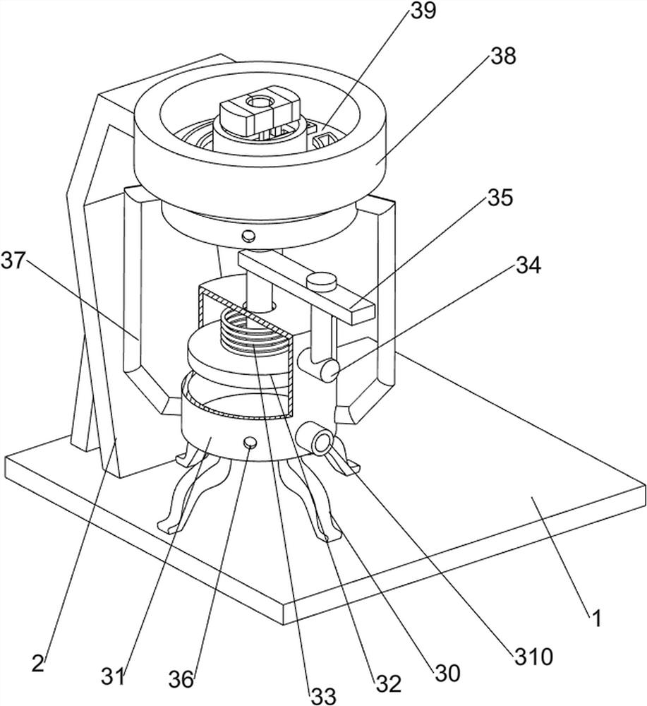
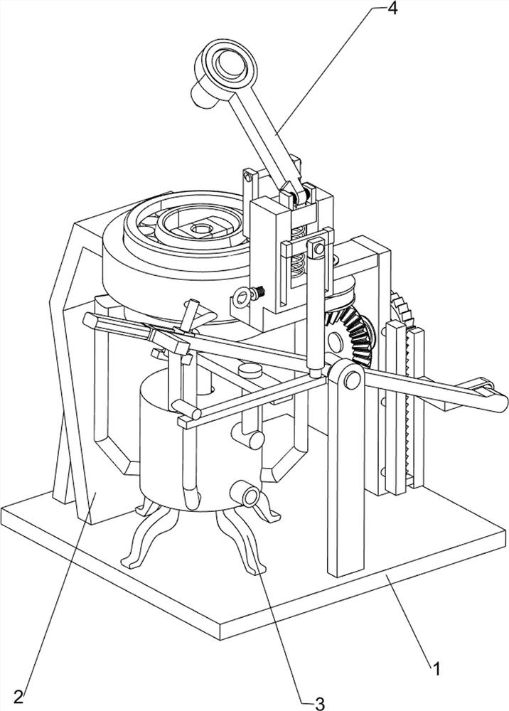
[0022] A bearing oiling device, such as figure 1 As shown, it includes a bottom plate 1, a bracket 2, an oiling assembly 3 and a clamping assembly 4. A bracket 2 is provided on the rear side of the top of the bottom plate 1. An oiling assembly 3 is installed in the middle of the top of the bottom plate 1. The oiling assembly 3 is connected to the bracket 2. The bottom plate 1 A clamping assembly 4 is installed on the front side of the top, and the clamping assembly 4 is connected with the oil injection assembly 3 .

[0023] When people need to fill the bearing with oil, people first pour the lubricating oil into the parts of the oil injection assembly 3, then place the bearing on the parts of the oil injection assembly 3, and then press down the parts of the clamping assembly 4 by hand to clamp The parts of the clamping assembly 4 move downward to press the bearing on the parts of the oil injection assembly 3, and at the same time, the parts of the clamping assembly 4 move dow...

Embodiment 2

[0025] On the basis of Example 1, such as Figure 2-4 As shown, the oil injection assembly 3 includes a base 30, a piston cylinder 31, a piston rod 32, a first spring 33, a guide rod 34, a pressure plate 35, an oil outlet pipe 37, a placement sleeve 38, an oil outlet sleeve 39 and a one-way valve 310, and a bottom plate 1 The base 30 is evenly arranged on the left side of the top, the number of the bases 30 is 4, the piston cylinder 31 is connected between the tops of the bases 30, the top of the piston cylinder 31 is slidingly connected to the piston rod 32, the bottom of the piston rod 32 and the top of the inner wall of the piston cylinder 31 A first spring 33 is connected between them, a guide rod 34 is connected to the upper side of the front part of the piston cylinder 31, and a pressure plate 35 is slidingly connected to the guide rod 34. Oil outlet hole 36, the quantity of oil outlet hole 36 is 4, oil outlet pipe 37 is connected in the middle part of oil outlet hole 36...

Embodiment 3

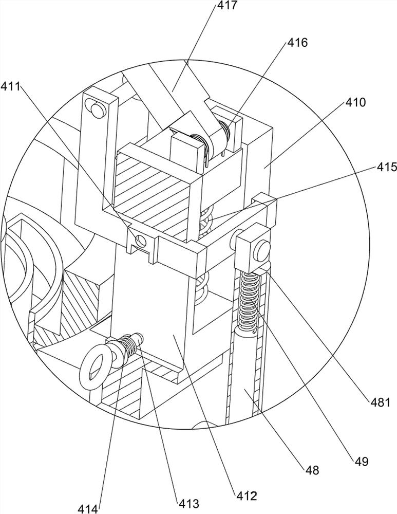
[0030] On the basis of Example 2, such as Figure 5 Shown, also includes rotating assembly 5, and rotating assembly 5 includes slide block 50, ratchet rack 51, mount 52, ratchet gear 53, guide block 54, full gear 55, second rotating shaft 56, bevel gear 57 and belt pulley Group 58, base plate 1 top right side is provided with mounting seat 52, and mounting seat 52 front lower side is connected with guide block 54, and guide block 54 right part is slidably connected with spine rack 51, and spine rack 51 front upper side is provided with Sliding block 50, sliding block 50 is connected with the sliding type of the right side rear part of warping rod 46, and the right part of the upper side of the mounting base 52 is connected with the spine gear 53 in a rotational manner, and the spine gear 53 is meshed with the spine rack 51, and the spine gear 53 left Full gear 55 is provided, and the left side of mounting base 52 is connected with the second rotating shaft 56 in a rotational m...


PUM


Abstract

The invention relates to an oil injection device, in particular to a bearing oil injection device. Provided is a bearing oiling device capable of compressing the bearing, filling the bearing with oil, evenly spreading the lubricating oil on the surface of the bearing, and preventing mis-collision. A bearing oiling device, comprising a bottom plate and a bracket, the top of the bottom plate is provided with a bracket; an oil injection component is installed in the middle of the top of the bottom plate, and the oil injection component is connected with the bracket; a clamping component is installed on the side of the top of the bottom plate away from the bracket. Assemblies, the clamping assembly is connected with the oiling assembly. With the cooperation of the oil injection assembly, the clamping device, the rotating assembly, the gear lever, the stopper and the sixth spring, the present invention can realize pressing the bearing, injecting lubricating oil into the bearing, rotating the lubricating oil on the surface of the bearing evenly and preventing misuse of the bearing. The impact causes the waste of lubricating oil, which makes the lubricating oil on the surface of the bearing more uniform, which is convenient for people to fill the bearing with oil, and avoids that some places are not coated with lubricating oil.

Description

technical field [0001] The invention relates to an oil injection device, in particular to a bearing oil injection device. Background technique [0002] Bearing is an important part of contemporary mechanical equipment. Its main function is to support the mechanical rotation, reduce the friction coefficient during its movement, and ensure its rotation accuracy. In order to ensure that the bearing installed on the journal works normally under lubrication , people will seal the bearing, but after the sealed bearing works for a long time, the grease sealed in the sealing ring will leak, so that the bearing cannot work normally, so it is necessary to inject lubricating oil into the bearing. The general lubricating oil injection method , is that people fix the bearing by hand or machine, and then oil the bearing. This method generally cannot make the lubricating oil on the surface of the bearing be evenly smeared, and the operation is complicated, and the work efficiency of bearin...

Claims


Application Information

Patent Timeline
Patent Type & Authority Patents(China)
IPC IPC(8): F16N7/14F16N21/00
CPCF16N7/14F16N21/00F16N2210/14
Inventor 黄德来
Owner CHANGSHA MEGE BEARINGS
Why Eureka
Try Eureka