
Improved carpenter clamp

A woodworking clip and positioning plate technology, applied in the field of machinery, can solve the problems of inconvenient use, inconvenient conversion of pressing and support, low working speed of woodworking clips, etc., and achieves the effect of convenient use.

Inactive Publication Date: 2010-03-31
上海朝华工具有限公司
View PDF0 Cites 3 Cited by
  • Summary
  • Abstract
  • Description
  • Claims
  • Application Information

AI Technical Summary

Problems solved by technology

[0003] The object of the present invention is to provide an improved woodworking clamp, which solves the technical problems of low working speed, inconvenient use, and inconvenient switching between compression and support in the prior art.

Method used


Image

  • Improved carpenter clamp
  • Improved carpenter clamp

Examples


Embodiment 1

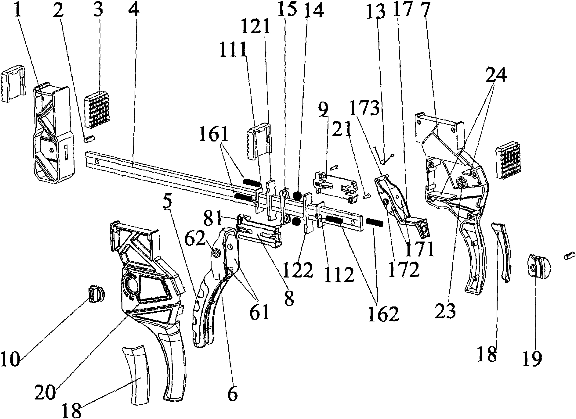
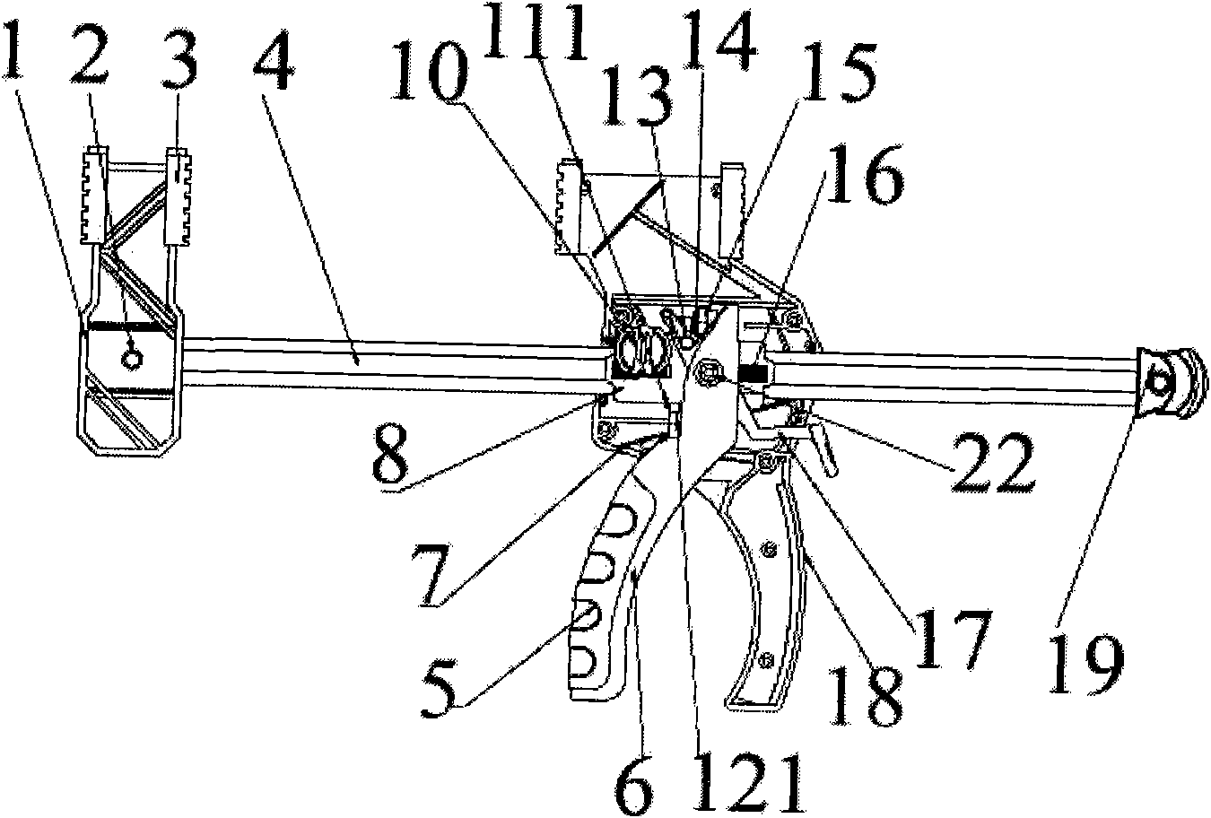
[0015] Such as figure 1 and figure 2 As shown, an improved woodworking clamp of the present invention is composed of a straight slide bar 4, a fixed pincer arm 1, a movable pincer arm 7 and a driving device, and the fixed pincer arm 1 is fixedly arranged on the straight slide bar 4, the movable pincer arm 7 is fixedly arranged on the top of the driving device, and the driving device is sleeved on the straight sliding rod 4, wherein the section of the straight sliding rod 4 is rectangular, and the driving device is composed of a shell body 20, driving block 8 and driving handle 6, the lower part of the outer casing 20 is fixedly provided with a fixed handle 18, the driving block 8 is arranged in the outer casing 20, and both ends of the outer casing 20 are provided with The housing through hole, the straight slide rod 4 passes through the housing through hole, the driving handle 6 is composed of a lever 61, and the fulcrum of the lever 61 is provided with a shaft 62, so The ...


PUM


Abstract

An improved carpenter clamp is composed of a straight slide bar, a fixing caliper arm, a flexible caliper arm and a driving device. The flexible caliper arm is fixedly arranged on the driving device,the driving device is sheathed at the straight slide bar, the driving device is internally provided with two positioning plates and a lever, the positioning plates are provided with rectangular holeswith the height all being larger than that of the straight slide bar, the positioning plates are sheathed at the straight slide bar through the rectangular holes, the lever is provided with a lower push face and an upper push face, simultaneously, the lower push face contacts with one positioning plate, or the upper push face contacts with the other positioning plate, the positions of the two positioning plates are changed by a knob shell connected with a deflector rod, one end of the each positioning plate is meshed with the straight slide bar after inclined by force, thus pushing the straight slide bar and the driving device to shift relative to each other. The invention selects toward motion or backward motion of the flexible caliper arm and the fixing caliper arm by arranging the relative positions of the positioning plates and the lever, realizing clamping and supporting functions and convenient use.

Description

Technical field: [0001] The invention relates to the mechanical field, in particular to a woodworking clamp, in particular to an improved woodworking clamp. Background technique: [0002] Woodworking clamps are often used to hold and pressurize wood parts. In the prior art, the woodworking clamp is composed of a C-shaped pliers, a bolt is arranged in the jaw, the front end of the bolt is provided with a clamping end face, the tail end of the bolt passes through a hole in the arm of the clamp at one end, and the clamping end face is connected with the clamp at the other end. The arms constitute the clamping mechanism. When in use, it needs to be released by loosening the bolt, and clamped by tightening the bolt. The working speed is low and it is inconvenient to use. Invention content: [0003] The object of the present invention is to provide an improved woodworking clamp, which solves the technical problems of low working speed, inconvenient use, and inconvenient switch...

Claims


Application Information

Patent Timeline
Patent Type & Authority Applications(China)
IPC IPC(8): B27C9/00
Inventor 朱洪文
Owner 上海朝华工具有限公司
Learn More