Drive wheel speed detection sensor protection structure of power unit

A technology of speed detection and power unit, applied in the direction of speed/acceleration/shock measurement, brake, speed/acceleration/electric shock meter detailed information, etc., can solve the problem of large number of parts and achieve the effect of reducing the number of parts

Active Publication Date: 2010-03-31
HONDA MOTOR CO LTD
View PDF3 Cites 14 Cited by
  • Summary
  • Abstract
  • Description
  • Claims
  • Application Information

AI Technical Summary

Problems solved by technology

[0008] The guard plate is a separate part, and in order to securely fix it to the transmission case, it needs to be fixed with at least two bolts, resulting in a large number of parts and requiring installation work

Method used


Image

  • Drive wheel speed detection sensor protection structure of power unit
  • Drive wheel speed detection sensor protection structure of power unit
  • Drive wheel speed detection sensor protection structure of power unit

Examples


Embodiment Construction

[0060] Below, based on Figure 1~Figure 10 An embodiment of the present invention is described.

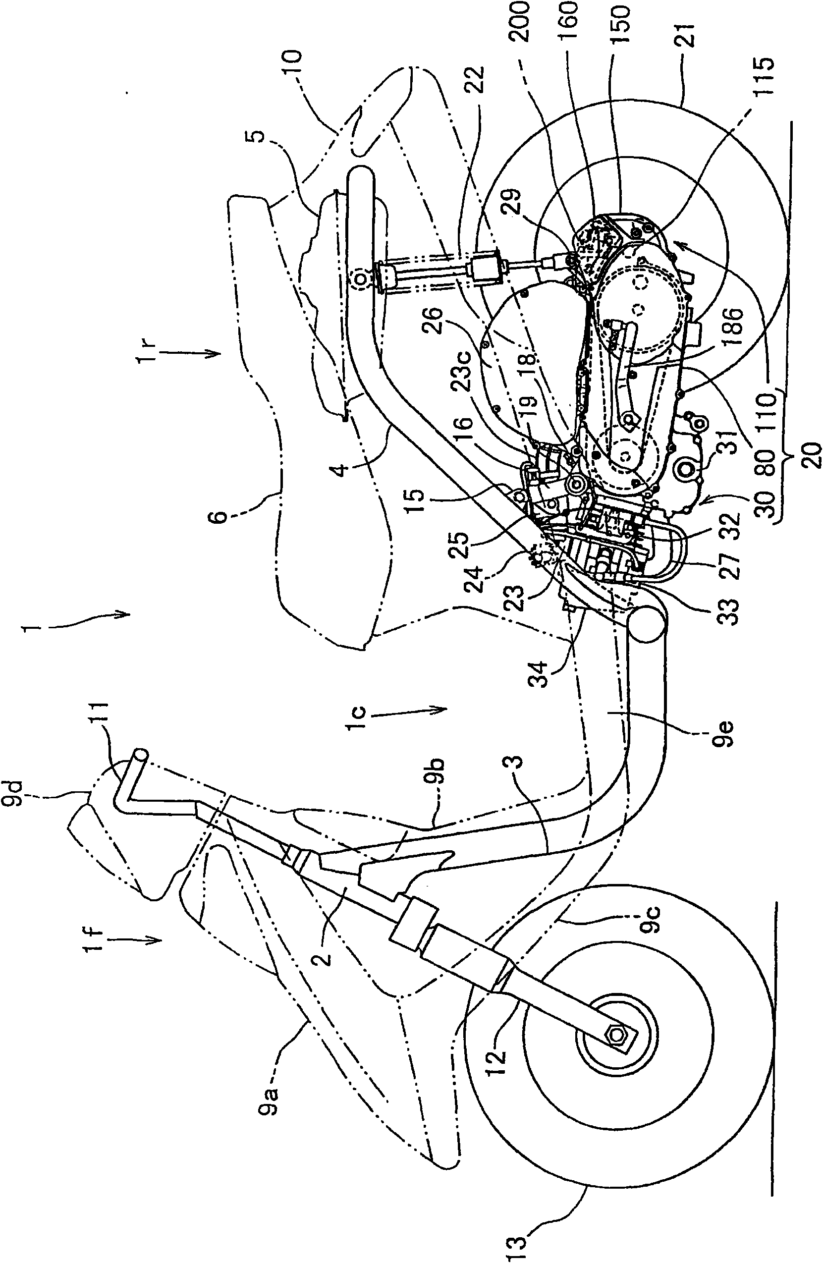
[0061] figure 1 It is a side view of a small motorcycle 1 applied to an embodiment of the present invention.

[0062] The vehicle body front portion 1f and the vehicle body rear portion 1r are connected via a low floor portion 1c, and the frame constituting the skeleton of the vehicle body is roughly composed of a down tube 3 and a main pipe 4.

[0063] That is, the down pipe 3 extends downward from the head pipe 2 of the front portion 1f of the vehicle body. The down pipe 3 is bent horizontally at the lower end and extends in the lower direction of the bottom plate portion 1c rearward. A pair of left and right main pipes are connected to the rear end of the down pipe 3 4. The main pipe 4 stands obliquely rearward from the connection part, bends horizontally at a predetermined height and extends backward.

[0064] A fuel tank 5 and the like are supported by this main pipe 4, and a seat 6 ...


PUM


Abstract

The invention provides a drive wheel speed detection sensor protection structure with a simple structure, which does not use a sole protection component and does not need installation operation. A back axle on the back section executes an axle suspension for a transmission case for containing a belt type stepless speed changer, and a drive wheel is embedded in a power unit which is installed on the back axle for supporting it. The forepart is supported by a vehicle frame axle and is swingly supported, according to rotation of the gear which is integrated with the back axle for detecting rotary speed of the drive wheel, and the drive wheel speed detection sensor embeds the frontend detection section into the transmission case and is installed for getting closer to the gear, and the drive wheel speed detection sensor protection structure is that: a protective wall is formed near the projecting section exposed towards outside of the self-transmission case of the drive wheel speed detection sensor, and is integrated with the transmission case and projects.

Description

Technical field [0001] The present invention relates to a structure for protecting a driving wheel speed sensor from flying foreign objects such as flying rocks. The driving wheel speed sensor is used to detect the speed of a driving wheel installed in a transmission box of a power unit. Background technique [0002] Generally, a structure of a power unit is known. The power unit is configured to house a belt-type continuously variable transmission in a transmission box extending from the front internal combustion engine to the rear, and to insert and mount the driving wheels on the rear axle shaft supported at the rear. And support it, and the front part of the power unit is pivotally supported by the frame of the two-wheeled motor vehicle and is swayably supported. [0003] And there is the following example, that is, a reduction gear mechanism is provided at the rear of the belt-type continuously variable transmission of the power unit, and the driving wheel speed sensor is inst...

Claims


Application Information

Patent Timeline
Patent Type & Authority Applications(China)
IPC IPC(8): B60T8/00B62J99/00G01P1/00B60T8/171B62K25/20F16H57/02F16H57/023G01P1/02
CPCB60T8/171
Inventor 小室广一土屋粒二山西辉英堀井宣孝
Owner HONDA MOTOR CO LTD
Why Eureka
Try Eureka