
Heat radiating control method of computer elements, program module and computer system

A control method and computer system technology, applied in auxiliary non-electric temperature control, temperature control using electric means, electric digital data processing, etc. Methods and products do not have appropriate methods and structures

Active Publication Date: 2010-03-31
ACER INC
View PDF0 Cites 7 Cited by
  • Summary
  • Abstract
  • Description
  • Claims
  • Application Information

AI Technical Summary

Problems solved by technology

[0004] 1. Adjusting the voltage of computer components due to overclocking can easily lead to system overheating problems: because the voltage of computer components that can be overclocked can be adjusted by the user, the computer system 9 The overall power distribution cannot be estimated properly, and as a result, the computer system will run the risk of overheating
[0005] 2. Existing temperature control technology cannot respond immediately to lower the system temperature: the current temperature control technology is that when the temperature increases, the speed of the fan also increases, and the temperature decreases At the same time, the speed of the fan also becomes lower. However, high temperature will be generated when the computer system 9 is restarted after the setting is completed. The existing computer temperature control technology cannot respond immediately and is easy to crash.
[0006] It can be seen that the above-mentioned existing heat dissipation control method of computer components and computer system obviously still have inconveniences and defects in the control method, product structure and use. and needs to be further improved
In order to solve the above-mentioned existing problems, relevant manufacturers have tried their best to find a solution, but no suitable design has been developed for a long time, and there is no suitable method and structure for general methods and products to solve the above-mentioned problems. This is obviously a problem that relevant industry players are eager to solve

Method used


Image

  • Heat radiating control method of computer elements, program module and computer system
  • Heat radiating control method of computer elements, program module and computer system
  • Heat radiating control method of computer elements, program module and computer system

Examples


Embodiment Construction

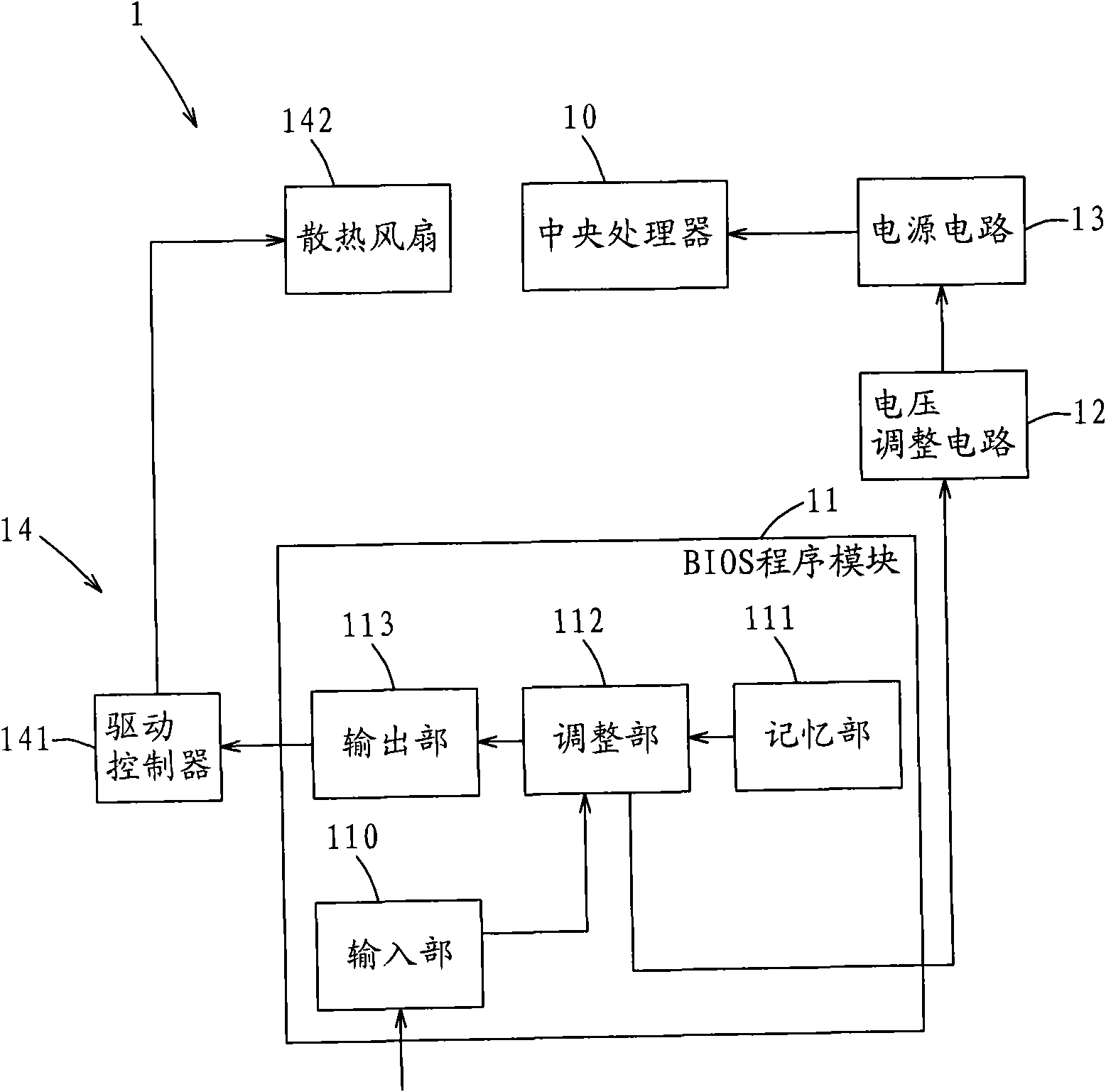
[0038] For further elaborating the technical means and effects that the present invention adopts for reaching the intended invention purpose, below in conjunction with accompanying drawing and preferred embodiment, to the heat dissipation control method of the computer component that proposes according to the present invention, program module and computer system its specific Embodiments, method steps, structural features and effects thereof are described in detail below.

[0039] The aforementioned and other technical contents, features and effects of the present invention will be clearly presented in the following detailed description of preferred embodiments with reference to the drawings. For convenience of description, in the following embodiments, similar elements are denoted by the same numerals.

[0040] It needs to be explained in advance that the concept of the heat dissipation control method for computer components of the present invention is used for the ratio of th...


PUM


Abstract

The invention relates to a heat radiating control method of compute elements, a program module and a computer system. A computer is provided with a heat radiating fan and the heat radiating control method of the computer elements comprises the following steps: (a) internally building at least one temperature control function of the computer elements, inputting an adjustable voltage value and correspondingly outputting a control parameter; (b) adjusting the adjustable voltage value of the computer elements and substituting the adjustable voltage value into the temperature control function to obtain a control parameter; and (c) outputting the control parameter and driving the heat radiating fan to cool the computer elements. The program module is matched with the heat radiating fan to execute the steps. The computer system contains the computer elements, a program module of a basic input and output system and a heat radiating device, wherein the program module is provided with an input part, a memory part, an adjusting part and an output part for outputting the control parameter; and the heat radiating device cools the computer elements according to the control of the control parameter. The invention can simultaneously and automatically control the temperature while adjusting the adjustable voltage value, immediately react to reduce the system temperature according to the controlparameter and can avoid the system overheating caused by adjusting the voltage.

Description

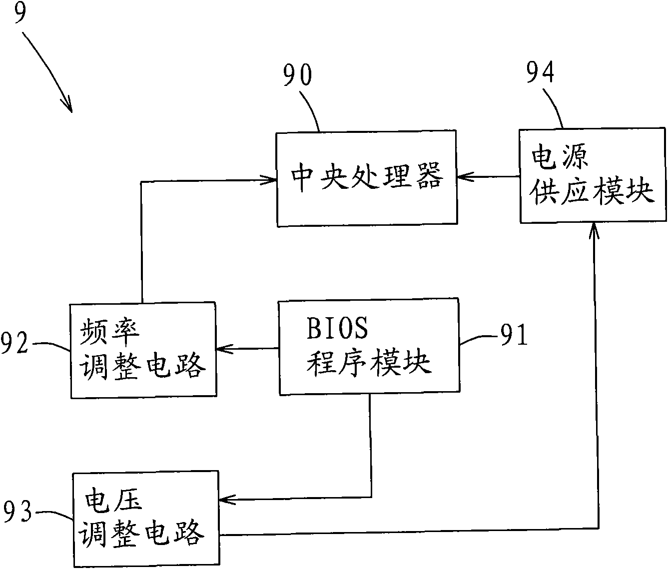
technical field [0001] The invention relates to a heat dissipation control method for computer components, a program module and a computer system, in particular to a heat dissipation control method, a program module and a computer system for computer components that can avoid the problem of system overheating caused by overclocking. Background technique [0002] see figure 1 Shown is a system block diagram illustrating that the frequency and voltage level of the computer components need to be set when the existing computer system overclocks the computer components. Existing computer system 9 is to specific computer components such as: when the central processing unit 90 is overclocked, in addition to setting the required frequency in the basic input output system (BIOS) program module 91, the central processing unit also needs to be set 90 voltage level (voltage level), then the frequency adjustment circuit (such as: overclocker) 92 correspondingly adjusts the frequency of ...

Claims


Application Information

Patent Timeline
Patent Type & Authority Applications(China)
IPC IPC(8): G06F1/20G05D23/19G05D23/185
Inventor 黄意惠江宜东
Owner ACER INC
Learn More