Main load-bearing structure suitable for ballistic reentry recovery capsule

A recovery cabin and main load-bearing technology, applied in space navigation equipment, space navigation vehicles, space navigation equipment, etc., can solve the problems of increasing the cost of testing and material processing, increasing the difficulty of design, increasing the weight of the structure, etc. , to achieve the effect of avoiding large loads, reducing component stress, and reducing stress concentration

Active Publication Date: 2017-02-22
BEIJING INST OF SPACECRAFT SYST ENG
View PDF4 Cites 6 Cited by
  • Summary
  • Abstract
  • Description
  • Claims
  • Application Information

AI Technical Summary

Problems solved by technology

[0005] (1) Strengthening the strength and rigidity of the installation structure will inevitably lead to an increase in its structural weight and a larger occupied space. For some parts with strict quality and space requirements, it will greatly increase the difficulty of design;
[0006] (2) When verifying through the ejection test, it is necessary to simulate the real state, which increases the cost of the test and material processing;
[0007] (3) The strengthening of the installation structure is only used to meet the impact of the projectile, but for other mechanical states, the performance is greatly enriched, resulting in a waste of design and not optimized enough

Method used


Image

  • Main load-bearing structure suitable for ballistic reentry recovery capsule
  • Main load-bearing structure suitable for ballistic reentry recovery capsule
  • Main load-bearing structure suitable for ballistic reentry recovery capsule

Examples


Embodiment Construction

[0039] The present invention will be described in detail below with reference to the accompanying drawings and examples.

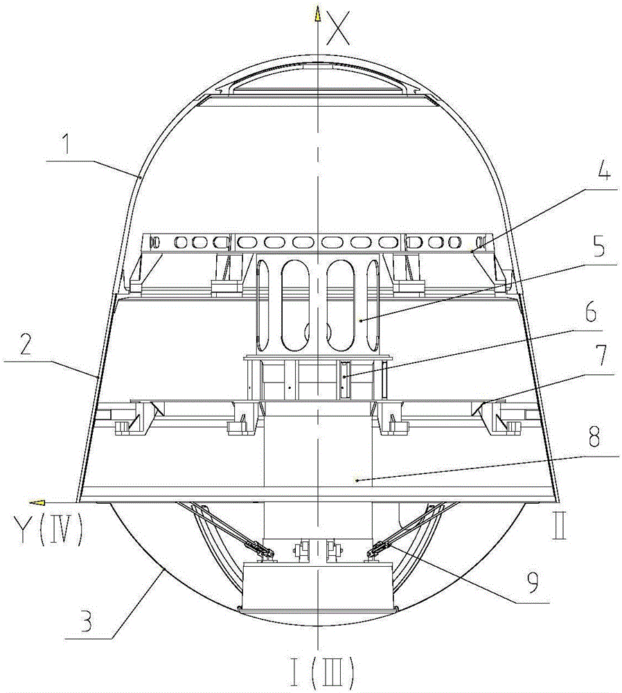
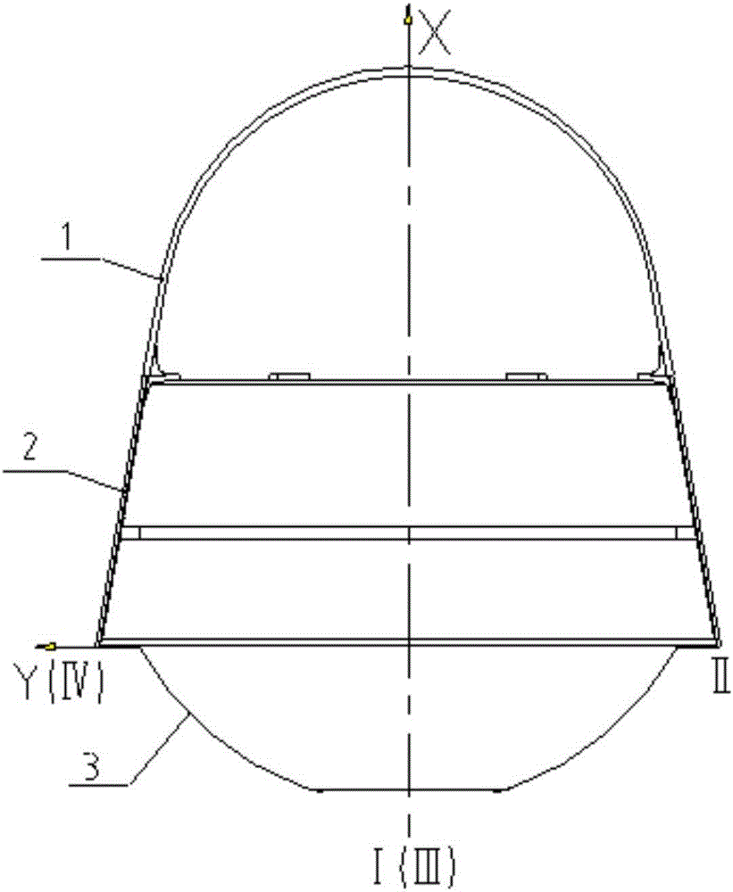
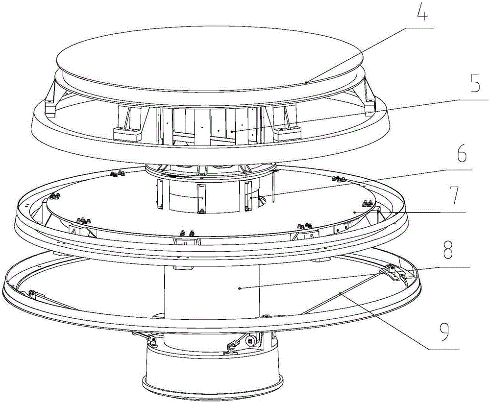
[0040] The invention provides a main load-bearing structure suitable for a ballistic reentry recovery cabin, see attached Figure 1-6 , including: head shell 1, stabilizing skirt 2, skirt bottom 3, instrument panel 4, transition bracket 5, support seat 6, platform 7, umbrella cabin device 8, pull rod 9 and adjusting gasket 10;

[0041] The head shell 1 is a shell composed of a truncated cone and a spherical segment, wherein the bottom surface of the spherical segment is docked with the small end of the truncated cone;

[0042] The stable skirt 2 is a frustum-shaped shell, and three annular bosses coaxial with the stable skirt 2 are processed on the inner peripheral surface of the stable skirt 2 along its axial direction, which are respectively the upper end frame and the middle spacer frame of the stable skirt 2. And the bottom end frame; The upper end fr...


PUM


Abstract

The invention discloses a main load-bearing structure suitable for a ballistic reentry recovery capsule, and belongs to the technical field of load bearing of a recovery capsule. The main load-bearing structure suitable comprises a head shell, a stabilizing flare, a flare bottom, an instrument panel, a transition bracket, a support base, a platform, a parachute bay device and a pull rod, wherein two ends of the stabilizing flare are respectively butted with the head shell and the flare bottom; the instrument panel is fixed to an upper end frame of the stabilizing flare; the transition bracket is coaxially mounted on the bottom surface of the instrument panel; the platform is connected with the middle bulkhead of the stabilizing flare; the support base is fixed to the upper surface of the platform; the support base is connected with the transition bracket; after a mounting end of the parachute bay device penetrates through the platform, the mounting end is connected with the support base and the transition bracket, and a parachute deployment end is connected with the stabilizing flare through the pull rod after penetrating through the stabilizing flare; a circular gap of the flare bottom is sealed by the spherical surface of the parachute deployment end of the parachute bay device; the structure can bear up under complicated reentry load conditions, meet the requirements of equipment mounting, increase the transversal fundamental frequency of the capsule body, and achieve lightweight design on the premise of satisfying rigidity and strength.

Description

technical field [0001] The invention belongs to the technical field of load-bearing of a recovery cabin, and in particular relates to a main load-bearing structure suitable for a ballistic reentry recovery cabin. Background technique [0002] The ballistic type of the main load-bearing structure of the ballistic reentry recovery module refers to the reentry and return mode without attitude control after entering the atmosphere. [0003] The re-entry recovery module must bear and transmit the launch load and escape load of the launch vehicle during launch, and it must bear loads such as overload, external pressure, and parachute opening impact when re-entering the atmosphere. Ballistic re-entry has its own characteristics. There is no attitude control measure during the re-entry process, which requires higher operational stability during the re-entry process. After entering the atmosphere, it is necessary to open the parachute to decelerate the cabin, and the moment the parac...

Claims


Application Information

Patent Timeline
Patent Type & Authority Applications(China)
IPC IPC(8): B64G1/22B64G1/66
CPCB64G1/22B64G1/66
Inventor 刘欣赵二鑫古青波张新星洪斌王晓姝赵会光邱家稳刘庆华
Owner BEIJING INST OF SPACECRAFT SYST ENG
Why Eureka
Try Eureka