Aero-engine turbine rotor cooling heat management system

A thermal management system, aero-engine technology, applied in the cooling of the engine, the cooling of the turbine/propulsion unit, the turbine/propulsion fuel delivery system, etc., can solve the problems of over-temperature of the turbine rotor of the aero-engine, and achieve easy transformation and implementation. Effect

Pending Publication Date: 2021-01-15
AECC SICHUAN GAS TURBINE RES INST
View PDF16 Cites 7 Cited by
  • Summary
  • Abstract
  • Description
  • Claims
  • Application Information

AI Technical Summary

Problems solved by technology

[0005] Purpose of the present invention: the present invention provides a cooling thermal management system for the turbine rotor of an aero-engine to solve the problem of over-temperature of the turbine rotor of an aero-engine in high-speed aircraft

Method used


Image

  • Aero-engine turbine rotor cooling heat management system
  • Aero-engine turbine rotor cooling heat management system
  • Aero-engine turbine rotor cooling heat management system

Examples


Embodiment Construction

[0026] The present invention will be described in further detail below by means of specific embodiments:

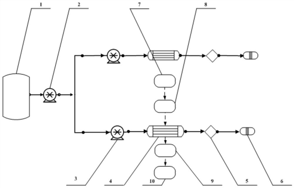
[0027] figure 1 Schematic diagram of the fuel flow path of the thermal management system, such as figure 1 As shown, in the thermal management system, the air-fuel heat exchanger 4 is added. When flying at high speed, the fuel in the fuel tank flows into the main fuel flow path and the afterburner fuel flow path respectively after passing through the first booster pump 2. The specific flow path The fuel flows from the fuel tank 1 through the first booster pump 2, and then divides into two paths, one into the main fuel flow path and the other into the afterburner fuel flow path (large fuel flow). In the afterburner fuel flow path, the afterburner fuel first enters the air-oil heat exchanger 4 from the second booster pump 3, then flows through the large-volume oil path to form the attachment 5, and finally enters the combustion chamber 6; The flow rate is large, and the f...


PUM


Abstract

The invention provides an aero-engine turbine rotor cooling heat management system. The heat management system comprises an air-oil heat exchanger (4) and a cooling air flow guide structure (17). Theair-oil heat exchanger (4) is installed between the outer side of a main combustion chamber outer case and a rotating shaft. The air-oil heat exchanger (4) communicates with an engine fuel flow path.The cooling air flow guide structure (17) is located between the outer side of the main combustion chamber outer case and the rotating shaft. The front end of the cooling air flow guide structure (17)is connected with a cooling air outlet (16) of the air-oil heat exchanger (4), and the rear end of the cooling air flow guide structure (17) is connected with a pre-spinning nozzle (9). The air-oil heat exchanger (4) is used for cooling air. By means of the aero-engine turbine rotor cooling heat management system, the problem that an aero-engine turbine rotor in a high-speed aircraft is overheated is solved.

Description

technical field [0001] The invention relates to the thermal management field of an aero-engine, in particular to an aero-engine turbine rotor cooling thermal management system. Background technique [0002] As the flight speed of aircraft becomes higher and higher, the problem of heat becomes more and more prominent in the design of aero-engines. The thermal management system plays an increasingly important role in aero-engines, and it is an important factor to ensure that the various systems of the engine can work normally. However, the traditional relatively simple thermal management scheme has been unable to meet the current working requirements under high-speed flight conditions. [0003] According to the analysis of existing data, when solving the problem of overheating of turbine rotors in foreign countries, heat exchangers are generally used to cool the air entering the turbine rotors with external air, or use air coolers with liquid nitrogen or helium cooling to coo...

Claims


Application Information

Patent Timeline
Patent Type & Authority Applications(China)
IPC IPC(8): F02C7/18F02C7/224
CPCF02C7/185F02C7/224
Inventor 马庆辉娄德仓赵维维苏云亮陈晖王锡铜
Owner AECC SICHUAN GAS TURBINE RES INST
Why Eureka
Try Eureka