
Microswitch

An electrical switch and reed technology, applied in the field of micro switches, can solve the problems of high design cost of switch design scheme, weakened switch function, increased production cost, etc., and achieve the effect of favorable design scheme, improved durable performance and simple cost

Inactive Publication Date: 2014-08-20
JOHNSON ELECTRIC OLDENBURG
View PDF7 Cites 0 Cited by
  • Summary
  • Abstract
  • Description
  • Claims
  • Application Information

AI Technical Summary

Problems solved by technology

External control is also required in order to perform a defined single action, but this often limits the switching function due to frictional hysteresis and causes a reduction in the switching function
In addition, the control of the contact spring in the actuation direction of the actuating element means that the design of the switch concept is too costly and the corresponding production costs are also increased

Method used


Image

  • Microswitch
  • Microswitch
  • Microswitch

Examples


Embodiment Construction

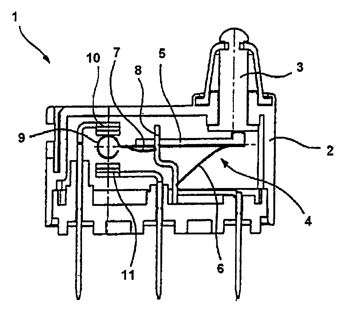
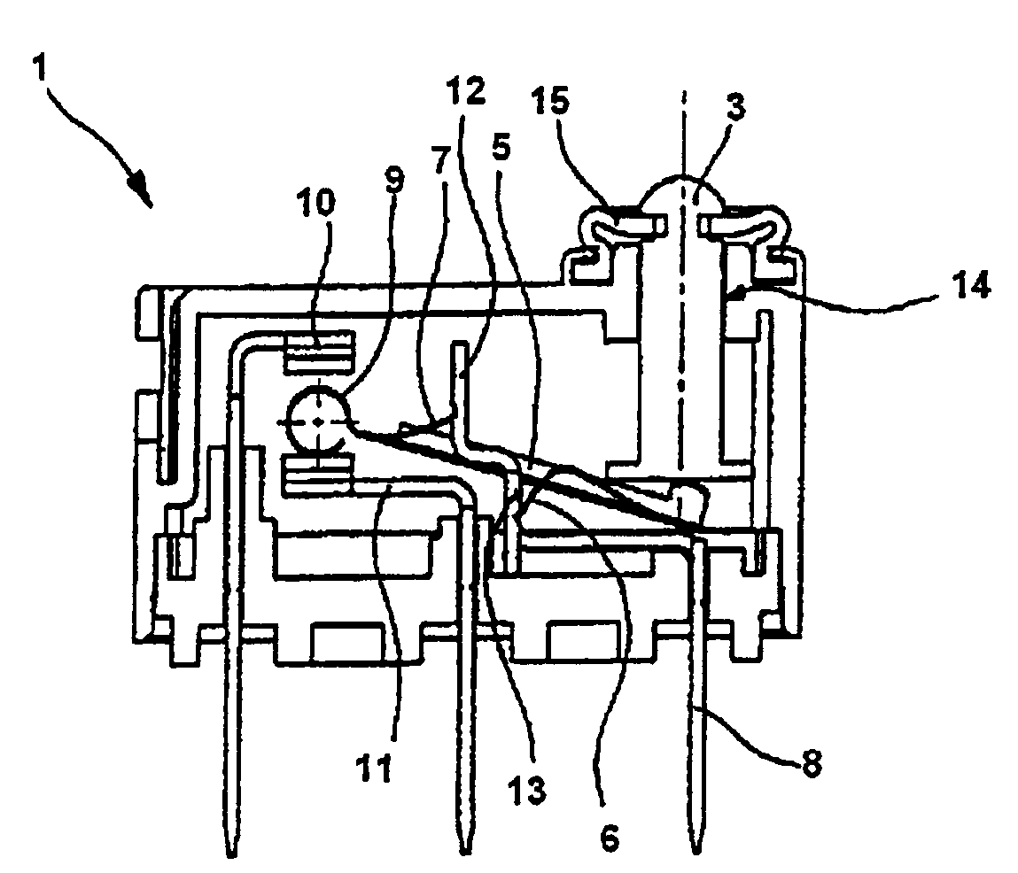
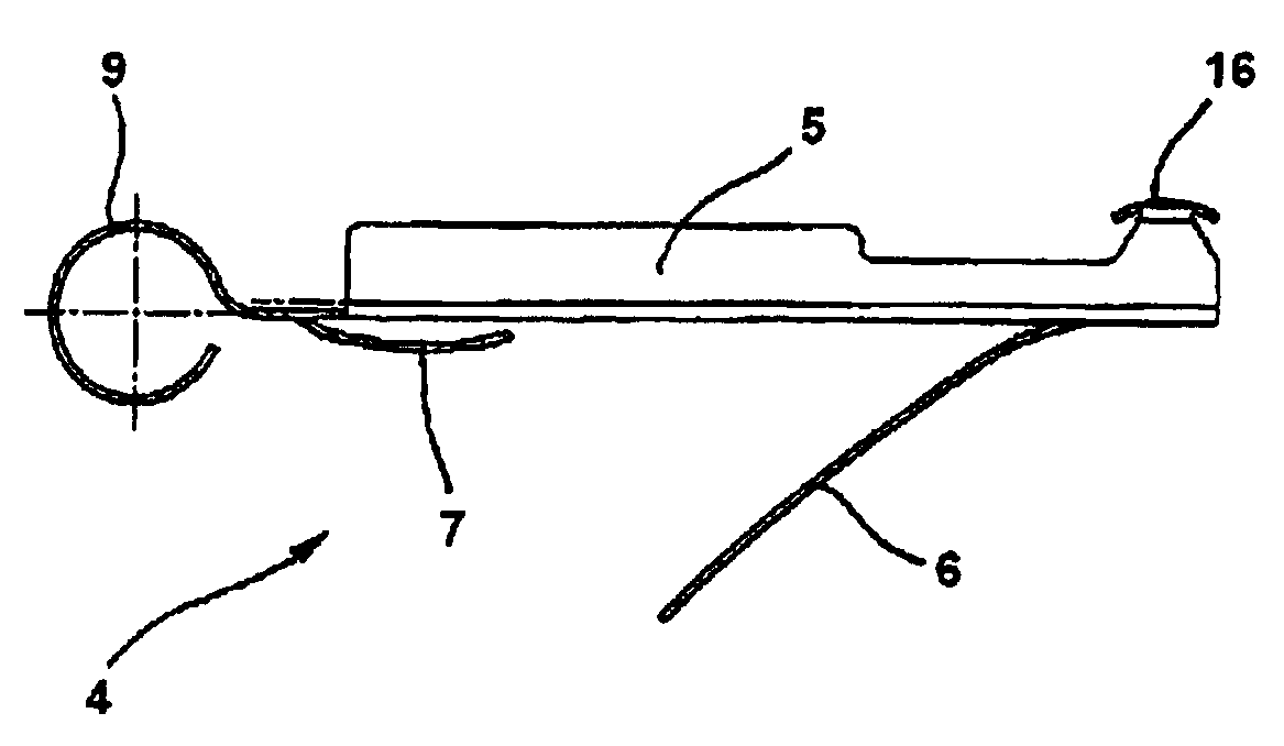
[0021] use figure 1 A microswitch is shown, which has at least one housing 2 and an actuating element 3 protruding into the housing, which in turn contacts a contact spring 4 which can be jumped over to different switching positions. bump. The contact spring 4 has a closed spring frame 5 on which two spring tongues 6 , 7 extending approximately in opposite directions are arranged in a flexible manner. The reed tongues 6 , 7 are preferably formed in one piece with the spring frame 5 and are supported on both sides on a carrier 8 designed as an electrical contact. In this case, the first reed tongue 6 is a longitudinally bent spring leaf which is loaded with compressive stress at least in its longitudinal direction, and which additionally serves as a return device for the actuator 3 . The second reed tongue 7 preferably controls the switching function of a contact area 9 formed on the contact spring 4 which can be switched back and forth between the upper contact 10 and the lo...


PUM


Abstract

The switch has contact springs (4) transferred into different switching positions by an actuating element and arranged at an anchor formed as an electrical contact. Spring tongues (6, 7) are arranged at a closed spring frame (5). One spring tongue is formed as a resetting unit for the actuating element. Another spring tongue controls switching functions of a contact region (9) of the springs. The tongues are engaged at surface regions of the anchor in a supporting manner such that the springs exhibit stable position during actuation, where the surface regions are turned away from each other.

Description

technical field [0001] The invention relates to an electric switch, especially a micro switch, the switch has at least one contact spring which can jump to different switching positions through an operating member, and the contact spring is mounted on a on the stand. Background technique [0002] In measuring technology, control and regulation technology, electrical switches of the above-mentioned construction are preferably used, such as microswitches or similar switches, which are often used for automatic determination with relatively high repeat accuracy in the corresponding supply and control circuits in these fields of application to complete the conversion process. The electrical switches used for these special switching processes generally have a contact spring which respectively determines the switching position of the microswitch and which provides a tilting action during operation. By changing the position of a mechanical actuator, e.g. a push rod protruding into...

Claims


Application Information

Patent Timeline
Patent Type & Authority Patents(China)
IPC IPC(8): H01H13/36
CPCH01H13/40H01H5/22
Inventor M·科普塞尔
Owner JOHNSON ELECTRIC OLDENBURG
Learn More