Cutting tool with a supporting body

A cutting tool and carrier technology, applied in the field of cutting tools, can solve problems such as uneven cutting and inability to provide, and achieve the effects of reducing tool cost, neat cutting, and improving spring efficiency

Inactive Publication Date: 2010-03-31
LEITZ GMBH & CO KG
View PDF0 Cites 4 Cited by
  • Summary
  • Abstract
  • Description
  • Claims
  • Application Information

AI Technical Summary

Problems solved by technology

[0004] As a result, the cutting edge vibrates during machining, which leads to uneven cutting; in extreme cases, chips can get between

Method used


Image

  • Cutting tool with a supporting body
  • Cutting tool with a supporting body
  • Cutting tool with a supporting body

Examples


Embodiment Construction

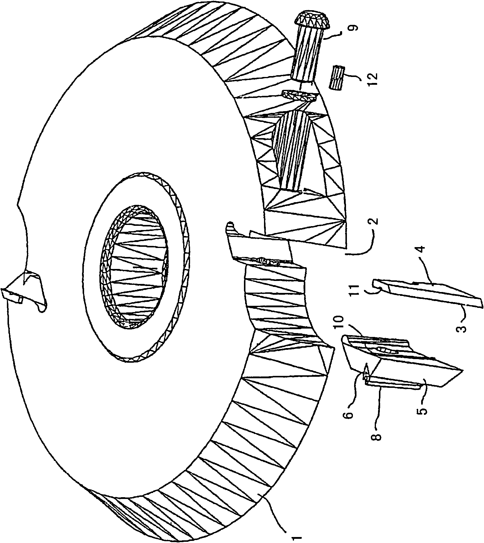
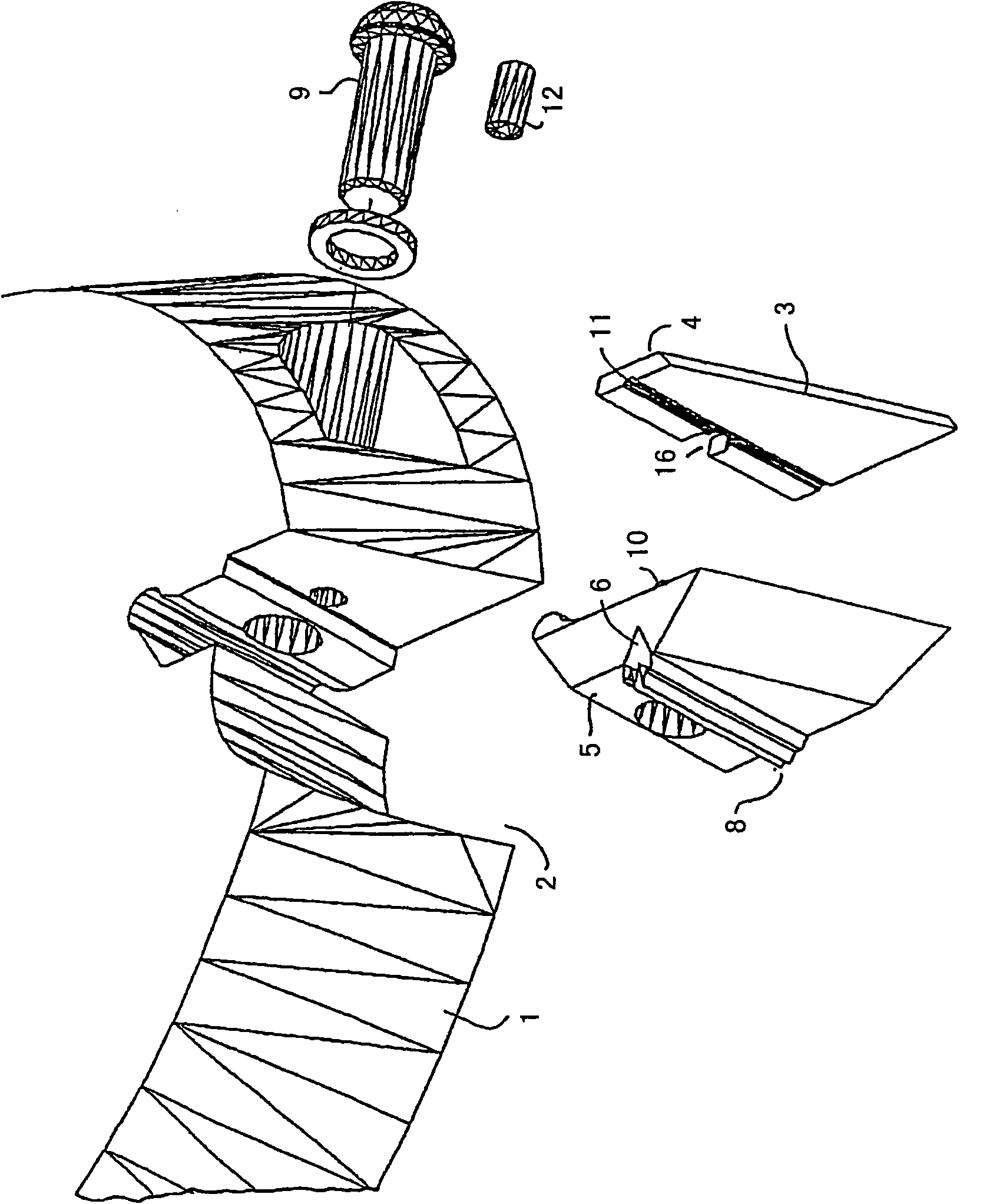
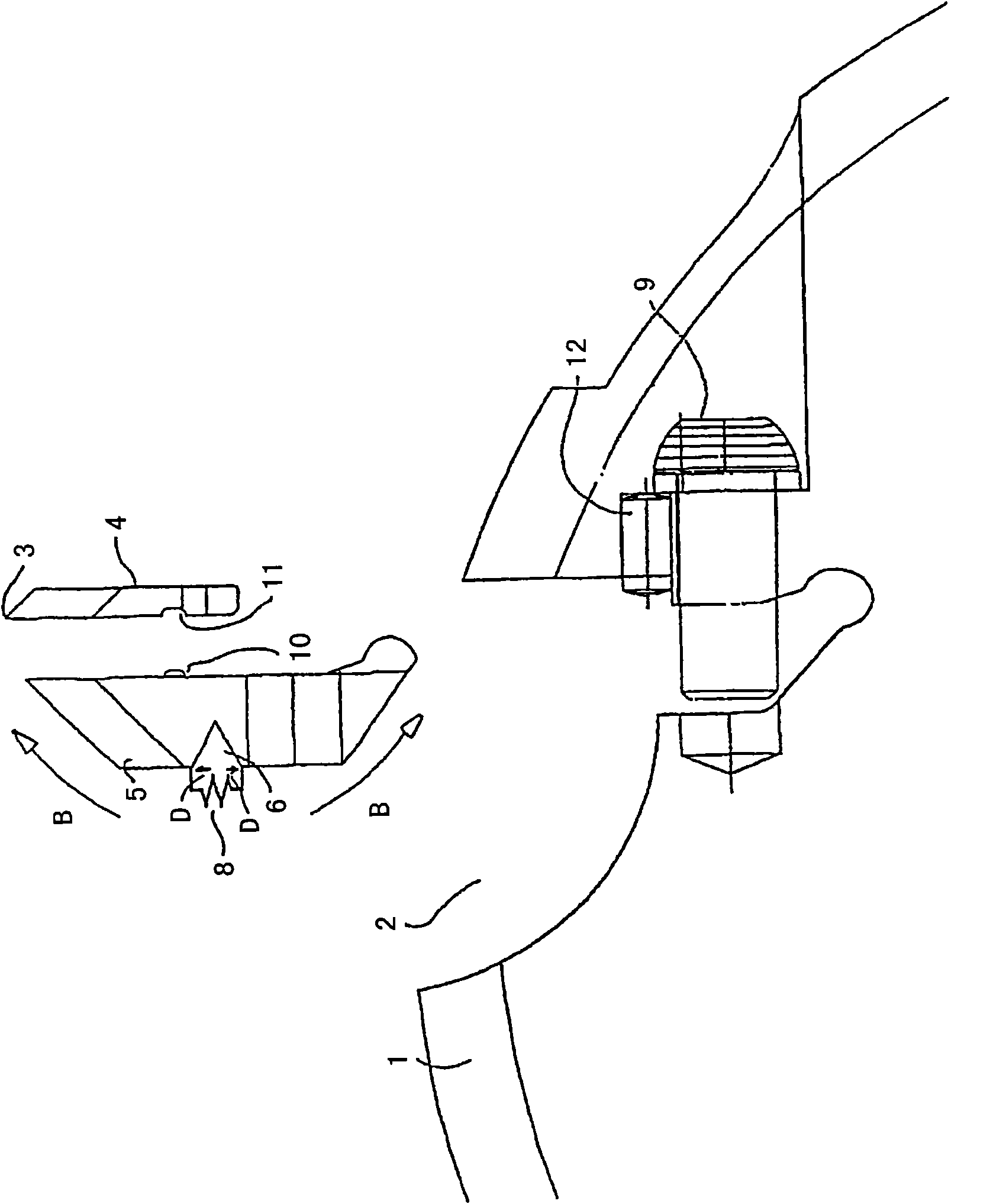
[0028] figure 1 A cutting tool is shown, which has a carrier body 1 and a receptacle 2 machined into the carrier body. The receptacle 2 can be formed either during the shaping process of the carrier body 1 or processed afterwards by milling, grinding or other processing methods. The receptacle 2 serves as a seat for a cutting element 4 whose cutting edge 3 extends radially outward from the carrier body 1 in the exemplary embodiment shown. In addition to the radially outwardly directed cutting edge 3 , the cutting edge 3 can extend radially inward, for example in the case of a whirl cutter.

[0029] The cutting element 4 is inserted into its seat, ie into the receptacle 2 , wherein a clamping jaw 5 is arranged opposite the seat, which clamps the cutting element 4 .

[0030] The clamping takes place by means of a screw 9 which engages through a through hole in the carrier body 1 into a thread formed in the clamping jaw 5 and clamps the cutting element 4 after applying a fixing...


PUM


Abstract

The invention relates to a cutting tool with a supporting body and at least one receptacle (2), which is arranged in the supporting body (1), is openly formed to allow a cutting edge (3) of a cuttingelement (4) to pass through and in which the cutting element (4) is clamped in its seat by means of at least one clamping jaw (5). The object of the invention is to improve the cutting tool with respect to the cutting behaviour and cost-effectiveness. This object is achieved by the cutting jaw (5) being formed resiliently in the direction of the cutting element (4).

Description

technical field [0001] The invention relates to a cutting tool according to the preamble of claim 1 . The invention also relates to a cutting element for such a cutting tool. Background technique [0002] Cutting elements of this type are known, in which a cutting element and a movable jaw are arranged in a carrier body in a formed receptacle, wherein the jaw clamps the cutting element in its seat by centrifugal force . In such cutting tools, the mounting and correct orientation of the cutting elements as well as dismounting are relatively complex and there is a risk of the cutting elements slipping off when the tool is stopped. [0003] Furthermore, cutting tools are known in which the cutting element is fixed in a receptacle of the carrier by means of a screw connection. It is important here that the contact surfaces of the jaws, of the cutting element and of the cutting element seat are designed to be flat in order to ensure a uniform contact pressure. In such cutting...

Claims


Application Information

Patent Timeline
IPC IPC(8): B27G13/10
CPCB27G13/10Y10T407/1934Y10T407/1932
Inventor R·帕奇Z·佩凯奇F·斯坦德勒
Owner LEITZ GMBH & CO KG
Why Eureka
Try Eureka