Fuel cell

A fuel cell and fuel technology, which is applied to fuel cells, fuel cell components, solid electrolyte fuel cells, etc., can solve problems such as position offset, the inability of sealing parts to be accurately embedded in the flow path, and the reduction of power generation efficiency of fuel cell systems. , to achieve the effect of suppressing mixing, not easy to position offset, and easy to locate

Inactive Publication Date: 2010-03-31
PANASONIC CORP
View PDF5 Cites 18 Cited by
  • Summary
  • Abstract
  • Description
  • Claims
  • Application Information

AI Technical Summary

Problems solved by technology

As a result, there is a problem that the power generation efficiency of the entire fuel cell system decreases
In addition, when the MEA and the separator are stacked, the extended sealing part may not be fitted into the flow path accurately, that is, the position may be shifted.

Method used


Image

  • Fuel cell
  • Fuel cell
  • Fuel cell

Examples


Embodiment approach 1

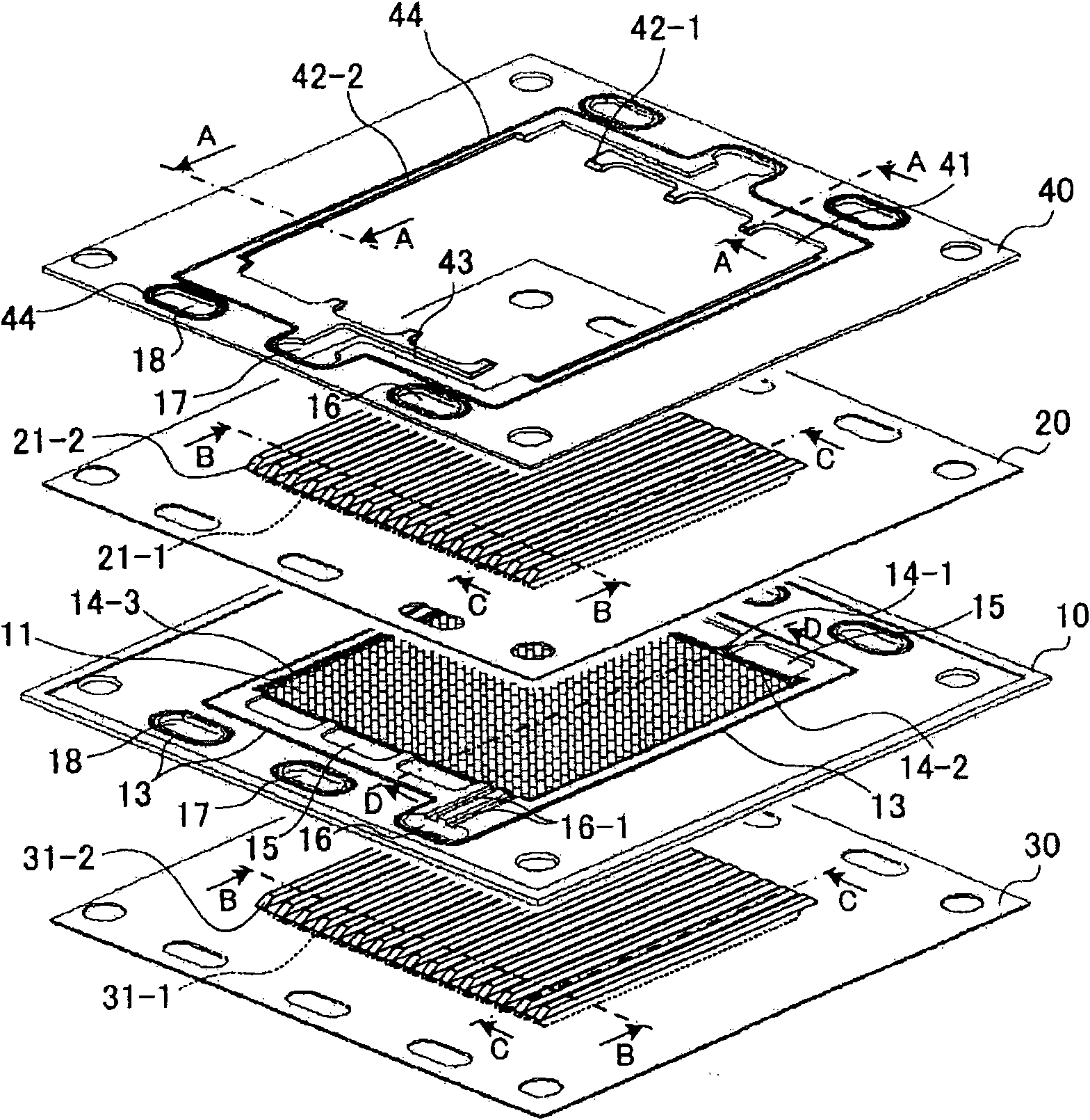
[0114] Figure 1A It shows the situation before lamination of the single fuel cell, in which 1) a linear flow path is formed in the center of each separator, and a turn-back portion of the flow path is formed on the frame holding the MEA, and 2) ) is provided with a spacer frame that allows cooling water to flow through the separator flow paths arranged between the fuel cells.

[0115] Figure 1A A plan view of each component of a frame holding an MEA (MEA holding frame) 10 , an anode separator 20 , a cathode separator 30 , and a separator frame 40 is shown.

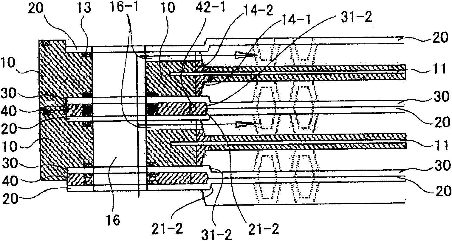
[0116] Figure 5A is the section at A of the isolation frame 40, Figure 5B is the section at B of separators 20 and 30, Figure 5C represents the cross-section at C of the separators 20 and 30, Figure 5D A cross section at D of the MEA holding frame 10 is shown.

[0117] The MEA holding frame 10 can be fabricated by forming a polypropylene frame (220 mm long x 220 mm wide) around the MEA 11 (for example, 150 mm l...

Embodiment approach 2

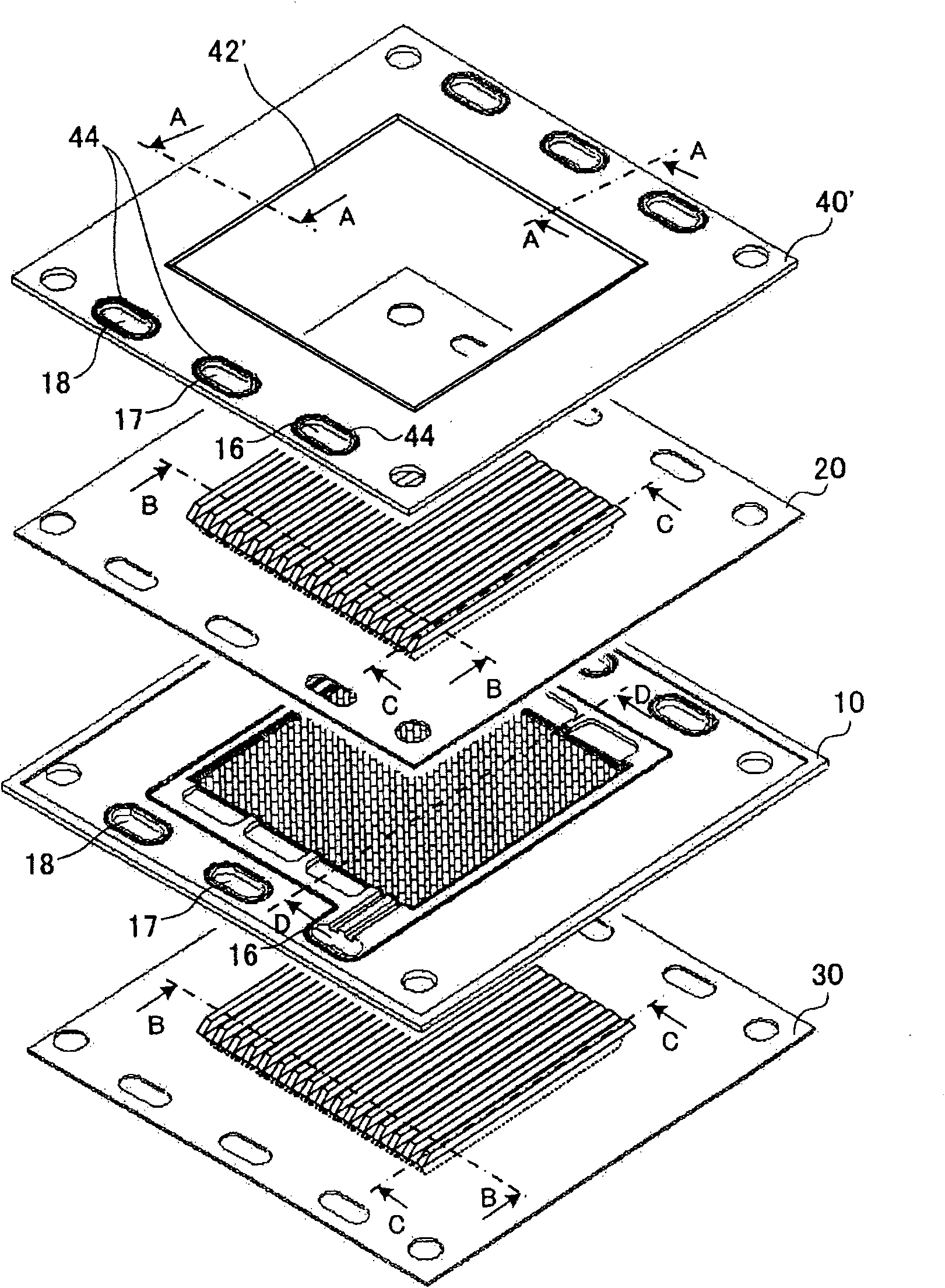
[0134] figure 2 The state before lamination of the single fuel cell is shown, and the single fuel cell has 1) a linear flow path formed in each separator, and a turn-back portion of the flow path formed in the frame holding the MEA, and 2) a The spacer frame is arranged between the fuel cells and does not allow cooling water to flow between the fuel cells.

[0135] figure 2 It is a top view of the MEA holding frame 10, the anode separator 20, the cathode separator 30, and the isolation frame 40'. The MEA holds the frame body 10, the anode separator 20, the cathode separator 30 and the single fuel cell of Embodiment 1 ( Figure 1A )same.

[0136] On the other hand, the difference is that, Figure 1A The illustrated single fuel cell has a spacer frame 40, whereas, figure 2 The illustrated fuel cell has a spacer frame 40'. That is, in the second embodiment, the cooling water of the fuel cell does not flow through the flow path between the stacked fuel cells. That is, co...

Embodiment approach 3

[0139] image 3 The state before lamination of single fuel cells is shown. The single fuel cells are 1) formed with linear flow paths in each separator and folded parts of the flow paths formed in the frame holding the MEA, and 2) arranged with a spacer frame arranged between the fuel cells and for allowing cooling water to flow through the separator flow path, and 3) forming only fuel gas manifold holes or oxidant gas manifold holes in each separator One of the manifold holes.

[0140] image 3 It is a plan view of the MEA holding frame 10, the anode separator 20', the cathode separator 30', and the isolation frame 40. The MEA holding frame 10, the spacer frame 40 and the single fuel cell ( Figure 1A ) in the same way.

[0141] on the other hand, image 3 The single fuel cell shown has an anode separator 20' and a cathode separator 30' in that it differs from a single fuel cell having an anode separator 20 and a cathode separator 30 (FIG. 1). That is, the fue...


PUM

PropertyMeasurementUnit
thicknessaaaaaaaaaa
thicknessaaaaaaaaaa

Abstract

Provided is a fuel cell using a metal separator, wherein the fuel cell more reliably suppresses leaks of the reaction gas without using excessive tightening force and has a simple structure. In a solid polymer single fuel cell having a frame protecting a membrane electrode assembly (MEA) and a metal separator: 1) The center portion of the separator faces the electrodes and forms a linear flow path, the outer periphery of the separator has a planar structure with a manifold hole. 2) The frame protecting the MEA is a sealing material covering the periphery of each electrode, and has the sealingmaterial in contact with the rib at the boundary of the center part and the outer periphery of the separator to regulate the flow of the reaction gas. 3) Each contact surface of the sealing material covering the electrode peripheries and the rib at the boundary between the center part and the outer periphery of the separator is inclined with respect to the layering direction from the frame to theseparator.

Description

technical field [0001] The present invention relates to a solid polymer fuel cell using a solid polymer electrolyte membrane. Background technique [0002] A fuel cell using a solid polymer electrolyte membrane is a battery that simultaneously generates electric energy and thermal energy by electrochemically reacting a hydrogen-containing fuel gas with an oxygen-containing oxidant gas such as air. Basic components include a polymer electrolyte membrane that selectively transports hydrogen ions, and a pair of electrodes sandwiching the polymer electrolyte membrane. Electrodes are often composed of a catalyst layer mainly composed of carbon powder that supports a platinum group metal catalyst, and a gas diffusion layer that has both air permeability and electron conductivity and is arranged outside the catalyst layer. [0003] In order not to leak the supplied fuel gas and oxidant gas to the outside or to prevent the two gases from mixing with each other, a gas seal or a gas ...

Claims


Application Information

Patent Timeline
Patent Type & Authority Applications(China)
IPC IPC(8): H01M8/02H01M8/10
CPCH01M8/0258H01M8/0273H01M8/0247Y02E60/521H01M8/242H01M8/248H01M8/1002H01M8/0263H01M8/0267H01M8/1007H01M8/2483Y02E60/50H01M8/02H01M8/10
Inventor 川畑德彦日下部弘树松本敏宏永井宏幸长尾善辉
Owner PANASONIC CORP
Why Eureka
Try Eureka