Discharging device of belt conveyor

A belt conveyor and unloading device technology, applied in the direction of transportation and packaging, conveyor objects, etc., can solve the problems of uneven unloading, wear of the belt surface of the belt conveyor, uneven friction between the scraper and the belt surface, etc., and achieve unloading Thoroughly, the effect of improving the service life of equipment

Inactive Publication Date: 2010-04-14
XINXING DUCTILE IRON PIPES CO LTD
View PDF0 Cites 4 Cited by
  • Summary
  • Abstract
  • Description
  • Claims
  • Application Information

AI Technical Summary

Problems solved by technology

In the actual production, the fixed-point material distribution form of the inclined conveyor belt conveyor is required, and the use of the plow unloader will not only cause serious wear on the belt surface of the belt conveyor, but also cause uneven discharge and uneven friction between the scraper and the belt surface. Problems such as machine deviation

Method used


Image

  • Discharging device of belt conveyor
  • Discharging device of belt conveyor
  • Discharging device of belt conveyor

Examples


Embodiment Construction

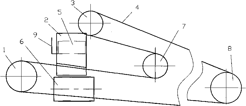
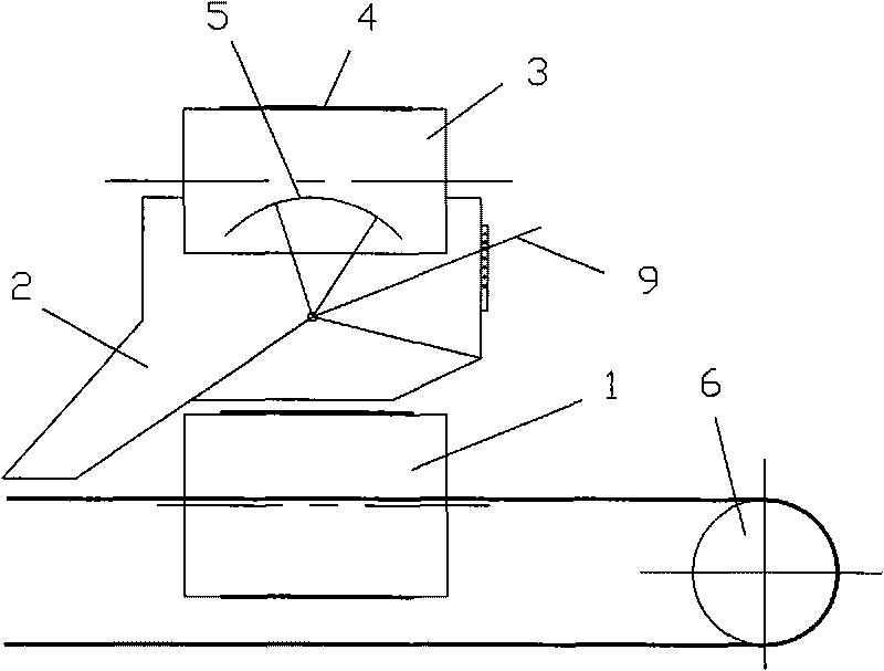
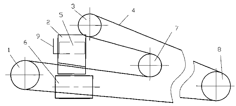
[0009] As shown in the drawings, it includes stockyard drum 8, discharge drum 3, reversing drum 7, drum 1 of belt conveyor one, belt conveyor two 6, discharge funnel 2, movable material distribution plate 5 and belt 4. The unloading drum 3, the reversing drum 7, and the drum 1 of the belt conveyor 1 are distributed in a triangle, the unloading drum 3 is on the top, and the belt 4 sequentially passes from the stockyard drum 8, the unloading drum 3, the reversing drum 7, and the belt conveyor 1. Drum 1 is bypassed, and the belt 4 between the stockyard drum 8 and the unloading drum 3 is a climbing section, which can raise the material level to facilitate unloading and material distribution. Belt 4 is a material distribution conveyor belt. There is a discharge funnel 2 on the lower left of the discharge drum 3, and there is a movable material distribution plate 5 at the entrance of the discharge funnel 2. The movable material distribution plate 5 is hinged with the discharge funne...


PUM


Abstract

The invention relates to a discharging device of a belt conveyor. A discharging roll, a turnabout roll and a roll of a charging belt 1 are distributed in a triangle shape, the discharging roll is arranged above, a belt sequentially moves around a stock ground roll, the discharging roll, the turnabout roll and the roll of the charging belt 1, the section of the belt between the stock ground roll and the discharging roll is a climbing section, the section of the belt between the turnabout roll and the roll of the charging belt is a distribution conveyor belt, a discharging funnel is arranged at the left below the discharging roll, the inlet of the discharging funnel is provided with a movable discharging board which is articulated with the discharging funnel, a control handle of the movable distribution board extends out of the discharging funnel, a plurality of adjusting holes of the control handle are arranged on the side wall of the discharging funnel; the discharging funnel is provided with a front discharging hole and a rear discharging hole, the lower end of the front discharging hole is provided with the distribution conveyor belt, and the lower end of the rear discharging hole is provided with a charging belt 2. The invention has thorough discharging, no friction with the belts during the distribution, and long service life of the belts.

Description

technical field [0001] The invention relates to an unloading device of a belt conveyor. Background technique [0002] At present, the unloading device of the belt conveyor usually uses a plow unloader and an electric unloading vehicle. The plow unloader is divided into three types: left, right and double-side unloading. This kind of unloader has a simple structure, but it wears a lot on the conveyor belt, especially when conveying abrasive materials and many unloading points, it should not be used. When choosing a plow unloader, a conveyor belt with a vulcanized joint should be used, and the speed should not exceed 2 m / s. Electric unloading trucks are suitable for unloading and distributing materials on multi-point horizontal conveyor belts. In actual production, the fixed-point material distribution form of the inclined conveyor belt conveyor is required, and the use of a plow unloader will not only cause serious wear on the belt surface of the belt conveyor, but also ca...

Claims


Application Information

Patent Timeline
Patent Type & Authority Applications(China)
IPC IPC(8): B65G47/34B65G47/52
Inventor 张树勋王素新
Owner XINXING DUCTILE IRON PIPES CO LTD
Why Eureka
Try Eureka