Portable giant magnetostrictive source device

A technology of giant magnetostrictive and giant magnetostrictive rods, applied in piezoelectric effect/electrostrictive or magnetostrictive motors, ultrasonic/sonic/infrasonic generation, electrical components, etc., can solve charging high voltage, discharging Problems such as limited time, output mechanical pulse energy dissipation, etc., achieve the effect of improving portability, reducing charging time, and finely adjusting pre-compression stress

Active Publication Date: 2012-02-01
武汉中岩科技股份有限公司
View PDF4 Cites 1 Cited by
  • Summary
  • Abstract
  • Description
  • Claims
  • Application Information

AI Technical Summary

Problems solved by technology

[0013] In summary, the giant magnetostrictive source device used in the anchor bolt detector in the prior art has a limited charging high voltage and a limited discharge time, and the three parts of the impact output rod, the control circuit, and the power supply module are equipped with a counterweight and a large-capacity The rechargeable battery and high-voltage capacitor must be designed separately, and its secondary threaded connection and guide head protector will dissipate the output mechanical pulse energy. These disadvantages need to be improved

Method used


Image

  • Portable giant magnetostrictive source device
  • Portable giant magnetostrictive source device
  • Portable giant magnetostrictive source device

Examples


Embodiment Construction

[0043]The technical solution of the present invention will be described in detail below in conjunction with the accompanying drawings and specific embodiments, so as to make the characteristics and advantages of the present invention more obvious. While the invention will be described in conjunction with examples, it will be understood that it is not intended to limit the invention to these examples. On the contrary, the invention is intended to cover various alternatives, modifications and equivalents as defined within the spirit and scope of the invention as defined by the appended claims.

[0044] Furthermore, in the following detailed description of the invention, numerous specific details are set forth in order to provide a thorough understanding of the invention. However, it will be understood by those skilled in the art that the present invention may be practiced without these specific details. In some other instances, well-known schemes, procedures, accessories and de...


PUM


Abstract

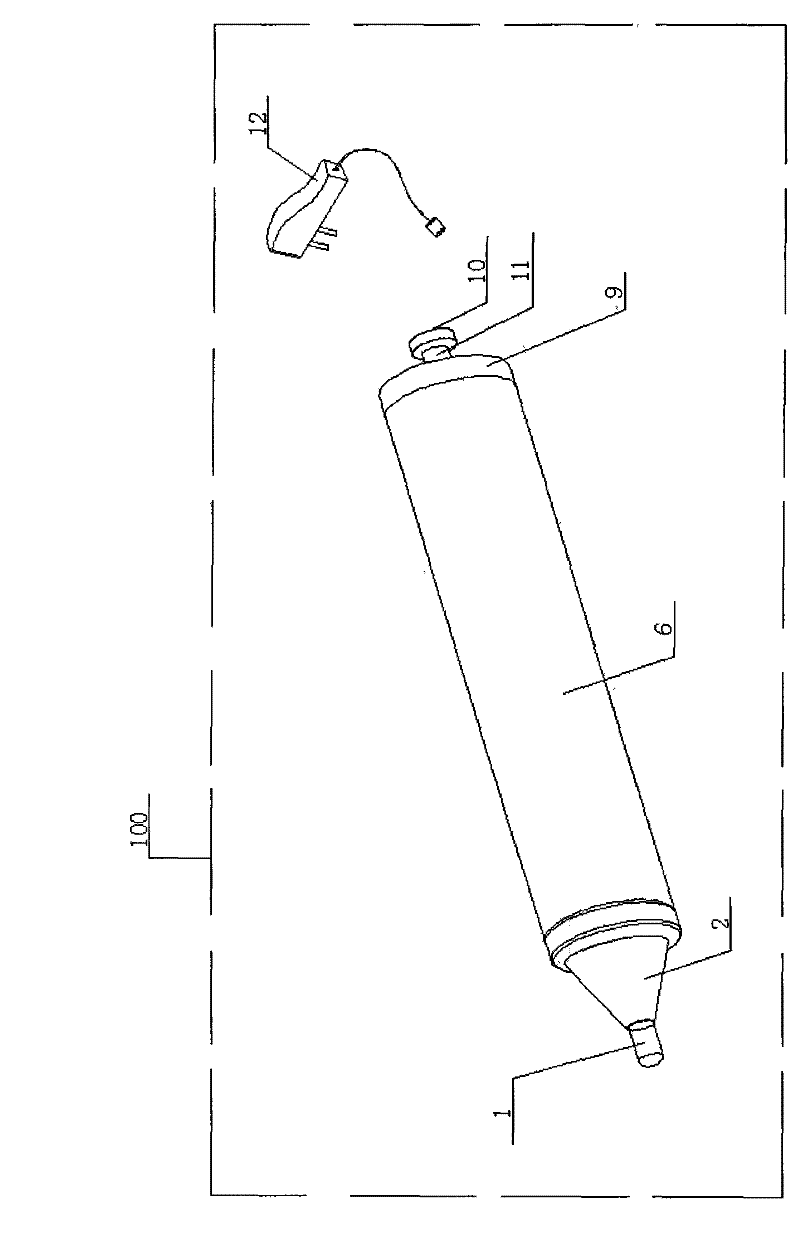
The invention discloses a portable giant magnetostrictive source device, which includes an impact output rod, a guide head guard, a pre-compressed stress adjustment plate, a giant magnetostrictive rod, a driving coil, an impact control circuit, a power supply module, and the impact control circuit and The driving coil is connected to the power supply module, the impact control circuit and the power supply module are installed in the shell, the impact output rod is connected with the guide guard, the shell, and the back cover in turn, the impact output rod is fixed by the guide guard, and the guide guard is a cone The bottom surface of the guide guard is connected to one end of the shell, and the giant magnetostrictive rod and the impact output rod are connected through a screw thread. The impact control circuit is placed in the middle of the cavity and connected with the driving coil and the power supply module. The power supply module is placed at the rear end of the cavity and connected with the driving coil and the impact control circuit. The invention improves the portability of the device, reduces the charging time, enhances the signal quality of the seismic source, improves the detection work efficiency, and is convenient for on-site operation and use.

Description

technical field [0001] The invention relates to the field of engineering detection instruments, and more specifically relates to a portable giant magnetostrictive source device, which is suitable for outputting instantaneous mechanical shock pulses and providing stress waves and ultrasonic sources for bolt detectors, acoustic wave detectors and other projects. Background technique [0002] Giant Magnetostrictive Material (GMM) is a new type of sensitive material made of the magnetostrictive effect of rare earth elements and metals to form compounds. It has the function of mutual conversion between electromagnetic energy and mechanical energy or acoustic energy. Rare earth giant magnetostrictive materials have the characteristics of large strain, large thrust, high electromechanical coupling coefficient, high energy conversion efficiency, good stability, and high reliability. They can be used in ultra-precision machining, robots, vibration and noise reduction, micro-electro-me...

Claims


Application Information

Patent Timeline
Patent Type & Authority Patents(China)
IPC IPC(8): G01N29/34H02N2/00H02N2/02
Inventor 胡纯军张杰
Owner 武汉中岩科技股份有限公司
Why Eureka
Try Eureka