Wire lead-in guide roller component of wire-drawing machine

A technology of wire drawing machine and guide roller, which is applied to wire drawing machine inlet guide roller assembly and wire inlet of wire drawing machine. It can solve problems such as unstable incoming line direction and affecting incoming line quality, and achieve the effect of simple structure, good transmission route, good economy and practicability

Inactive Publication Date: 2010-04-28
WUXI PINGSHENG SCI & TECH
View PDF0 Cites 2 Cited by
  • Summary
  • Abstract
  • Description
  • Claims
  • Application Information

AI Technical Summary

Problems solved by technology

In the current commonly used wire entry methods, there is instability in the direction of the incoming wire, which affects the quality of the incoming wire

Method used


Image

  • Wire lead-in guide roller component of wire-drawing machine
  • Wire lead-in guide roller component of wire-drawing machine
  • Wire lead-in guide roller component of wire-drawing machine

Examples


Embodiment Construction

[0010] The present invention will be further described below in conjunction with specific drawings and embodiments.

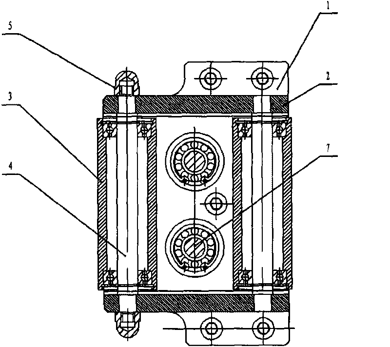
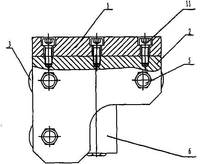
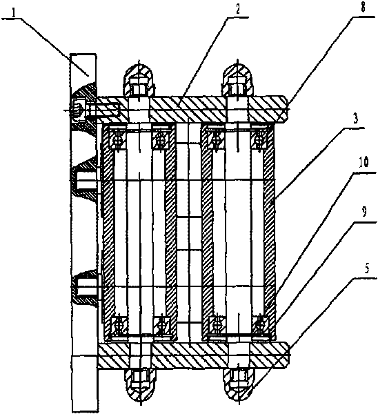
[0011] Such as Figure 1 ~ Figure 3 As shown: the present invention includes bottom plate 1, side plate 2, guide roller body 3, guide roller shaft 4, cap nut 5, bushing 6, mandrel 7, bearing 8, first elastic circlip 9, second elastic retainer Ring 10 and screw 11.

[0012] Such as figure 1 and image 3 As shown: the side plate 2 is located on the same side of the bottom plate 1 , and the side plate 2 is fixedly connected to the bottom plate 1 through screws 11 . Evenly and symmetrically distributed guide roller shafts 4 are arranged between the side plates 2 , and the guide roller shafts 4 are fixedly connected to the side plates 2 through cap nuts 5 . The guide roller body 3 is installed on the guide roller shaft 4 through the bearing 8 , and the guide roller shaft 4 locks the bearing 8 through the first circlip 9 and the second circlip 10 .

[0013] Such...


PUM


Abstract

The invention relates to a wire lead-in guide roller, in particular to a wire lead-in guide roller of a wire-drawing machine, which is particularly used for wire lead-in of the wire-drawing machine. According to a technical scheme provided by the invention, the wire lead-in guide roller comprises a substrate, wherein both ends of the substrate are provided with a lateral plate which is on the same side of the substrate and is fixedly connected with the substrate; guide roller shafts are uniformly and symmetrically distributed between the lateral plates and the two ends of the guide roller shafts are fixedly connected with the lateral plates; the guide roller shafts are provided with guide roller bodies through bearings positioned on two ends of the guide roller bodies; the roller bodies are provided first elastic retaining rings and second elastic retaining rings; and the bearings are tightly locked by the first elastic retaining rings and the second retaining rings. The wire lead-in guide roller component has the advantages that: the structure is simple, reasonable and compact, and the economy and practicality are high; and the guide roller shafts and guide roller bodies are arranged between the lateral plates, so the wire lead-in of the wire-drawing machine is stable, the delivery passages of the wire can be well controlled and the operation of the wire-drawing machine is stable.

Description

technical field [0001] The invention relates to a wire inlet guide roller, in particular to a wire inlet guide roller assembly for a wire drawing machine, in particular to a wire inlet for a wire drawing machine. Background technique [0002] In the prior art, there are many ways to enter the line. In the current commonly used wire entry methods, the direction of the incoming wires is unstable, which affects the quality of the incoming wires. Contents of the invention [0003] The purpose of the present invention is to overcome the disadvantages of the prior art, and provide a wire-drawing machine wire-feed guide roller assembly, which has a simple structure, compact and reasonable structure, and stabilizes the wire-feed of the wire-drawing machine. [0004] According to the technical solution provided by the present invention, a wire drawing machine inlet guide roller assembly includes a bottom plate; both ends of the bottom plate are provided with side plates, and the s...

Claims


Application Information

Patent Timeline
Patent Type & Authority Applications(China)
IPC IPC(8): B21C1/00
Inventor 顾康建
Owner WUXI PINGSHENG SCI & TECH
Why Eureka
Try Eureka