Floating ball funnel

A floating ball and funnel technology, which is applied in the field of experimental instruments, can solve the problems that the liquid cannot flow into the container, the liquid overflows, and the air cannot be discharged.

Inactive Publication Date: 2011-08-17
宁波市鄞州千峰机械科技有限公司
View PDF0 Cites 0 Cited by
  • Summary
  • Abstract
  • Description
  • Claims
  • Application Information

AI Technical Summary

Problems solved by technology

When pouring liquid into the deflector, especially when pouring a liquid with a high viscosity, the vertical pipe at the lower part of the deflector is often completely blocked by the liquid, so that the air in the container cannot be discharged and the liquid cannot flow in. container, even the liquid may overflow from the upper opening of the deflector

Method used


Image

  • Floating ball funnel
  • Floating ball funnel

Examples


Embodiment Construction

[0010] The present invention will be further described below in conjunction with the accompanying drawings and embodiments.

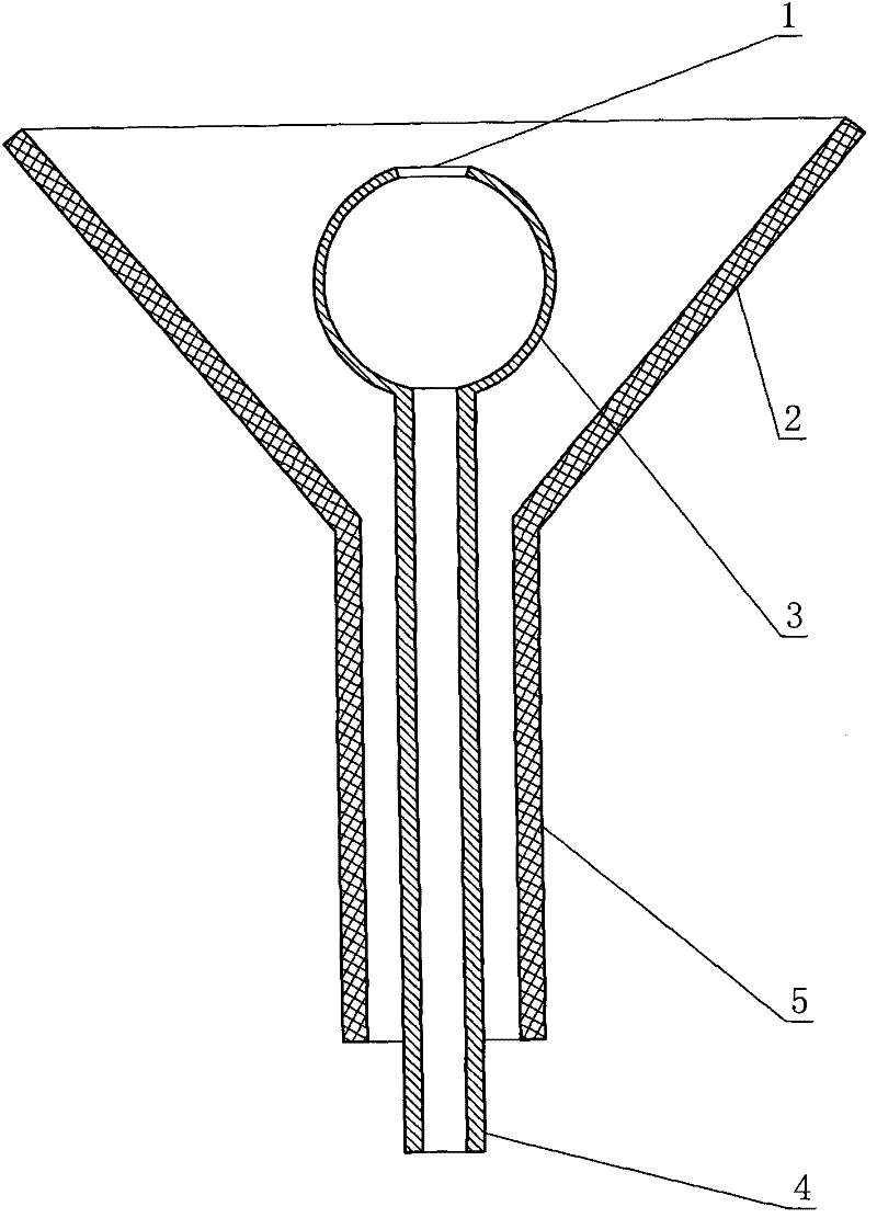
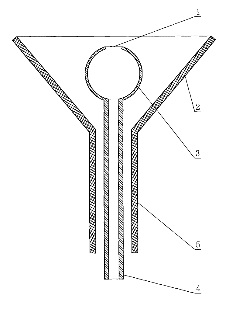
[0011] The float funnel is composed of an exhaust port 1, a tapered bucket 2, a float 3, an exhaust pipe 4 and a vertical pipe 5. The conical bucket 2 is an inverted conical shell, and the lower end of the conical bucket 2 is integrated with the cylindrical standpipe 5 . The circular tube-shaped exhaust pipe 4 is in the vertical pipe 5, and the top of the exhaust pipe 4 has a floating ball 3 which is integral with the exhaust pipe 4 and communicates with the exhaust pipe 4. The floating ball 3 is a spherical shell, and the top of the floating ball 3 has a The exhaust port 1 having a diameter larger than the inner diameter of the exhaust pipe 4 . The total length of the exhaust pipe 4 and the float 3 is greater than the total length of the tapered bucket 2 and the vertical pipe 5 .


PUM


Abstract

The invention relates to an experimental instrument, in particular to a floating ball funnel, which consists of an air outlet, a conical hopper, a floating ball, an exhaust pipe and a vertical pipe, wherein the conical hopper is an inversed conical shell; the lower end of the conical hopper and the cylindrical vertical pipe form a whole; the circular tubular exhaust pipe is positioned in the vertical pipe; the top end of the exhaust pipe is provided with the floating ball which is formed with the exhaust pipe integrally and is communicated with the exhaust pipe; the floating ball is a spherical shell; and the top end of the floating ball is provided with the air outlet. The total length of the exhaust pipe and the floating ball is greater than that of the conical hopper and the vertical pipe. When liquid is poured into the conical hopper, the liquid can flow into a container from a gap between the vertical pipe and the exhaust pipe so that the air in the container is exhausted from the air outlet through the exhaust pipe. The floating ball funnel puts an end to the blockage of the vertical pipe caused by viscous liquid.

Description

technical field [0001] The invention relates to an experimental instrument, in particular to a ball float funnel. Background technique [0002] In a chemical experiment, a deflector needs to be used when filling a liquid in a container with a small bottle mouth. The existing deflector is composed of an inverted conical shell and a vertical pipe at its lower part. When pouring liquid into the deflector, especially when pouring a liquid with a high viscosity, the vertical pipe at the lower part of the deflector is often completely blocked by the liquid, so that the air in the container cannot be discharged and the liquid cannot flow in. container, even the situation that the liquid overflows from the upper opening of the deflector also occurs. Contents of the invention [0003] In order to solve the deficiencies of the prior art, the invention provides a floating ball funnel with an instant exhaust function. [0004] The solution to the technical problem of the present inv...

Claims


Application Information

Patent Timeline
Patent Type & Authority Patents(China)
IPC IPC(8): B67C11/02
Inventor 许小玲
Owner 宁波市鄞州千峰机械科技有限公司
Why Eureka
Try Eureka