[0010]The present invention relates to an ejector system and controller for a vehicle, that inhibits the blockage of the ejector and adverse influence on the air-fuel ratio even if there is a time when the ejector does not operate. The vehicle ejector system and controller may be incorporated at minimal additional cost.
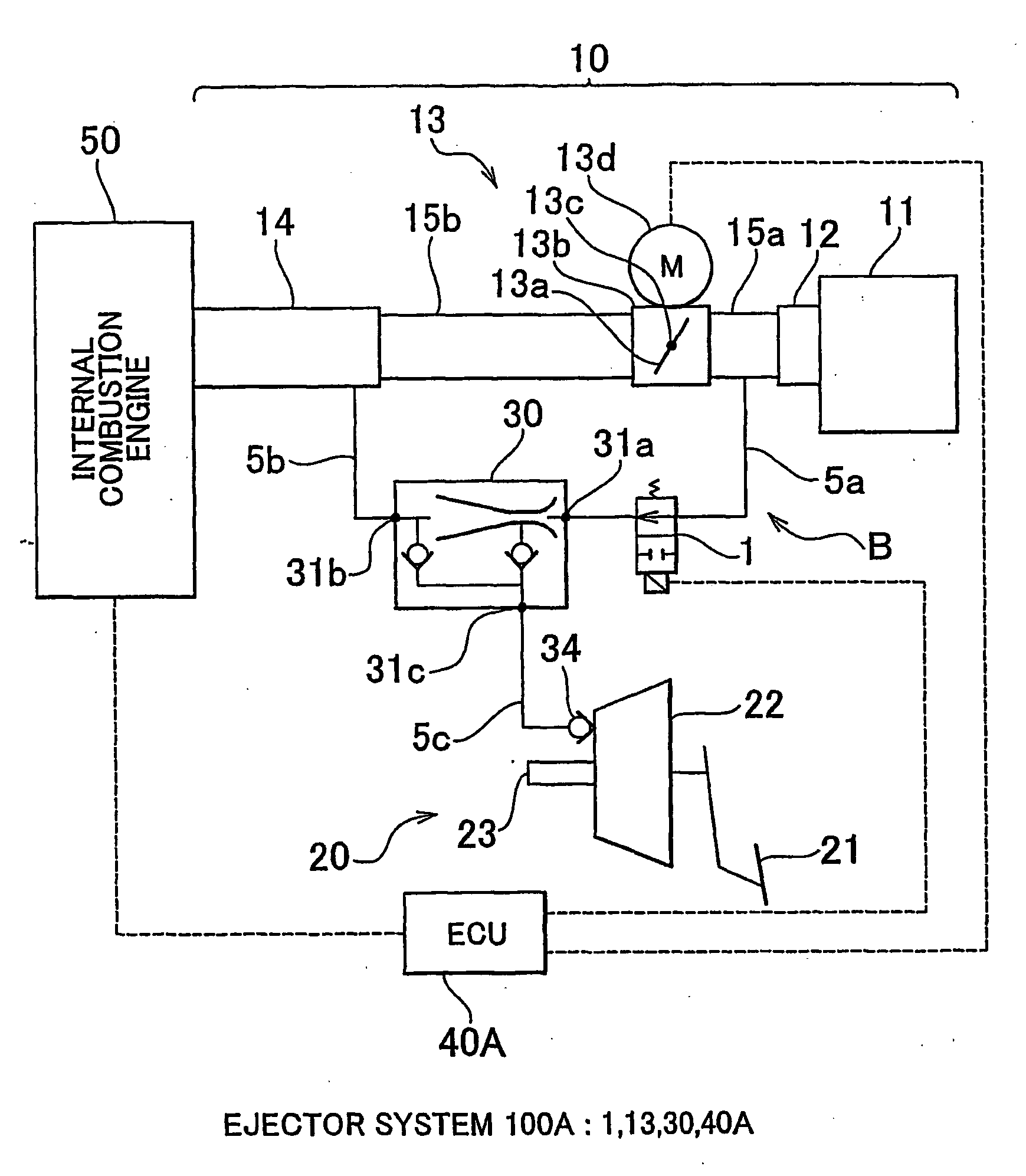
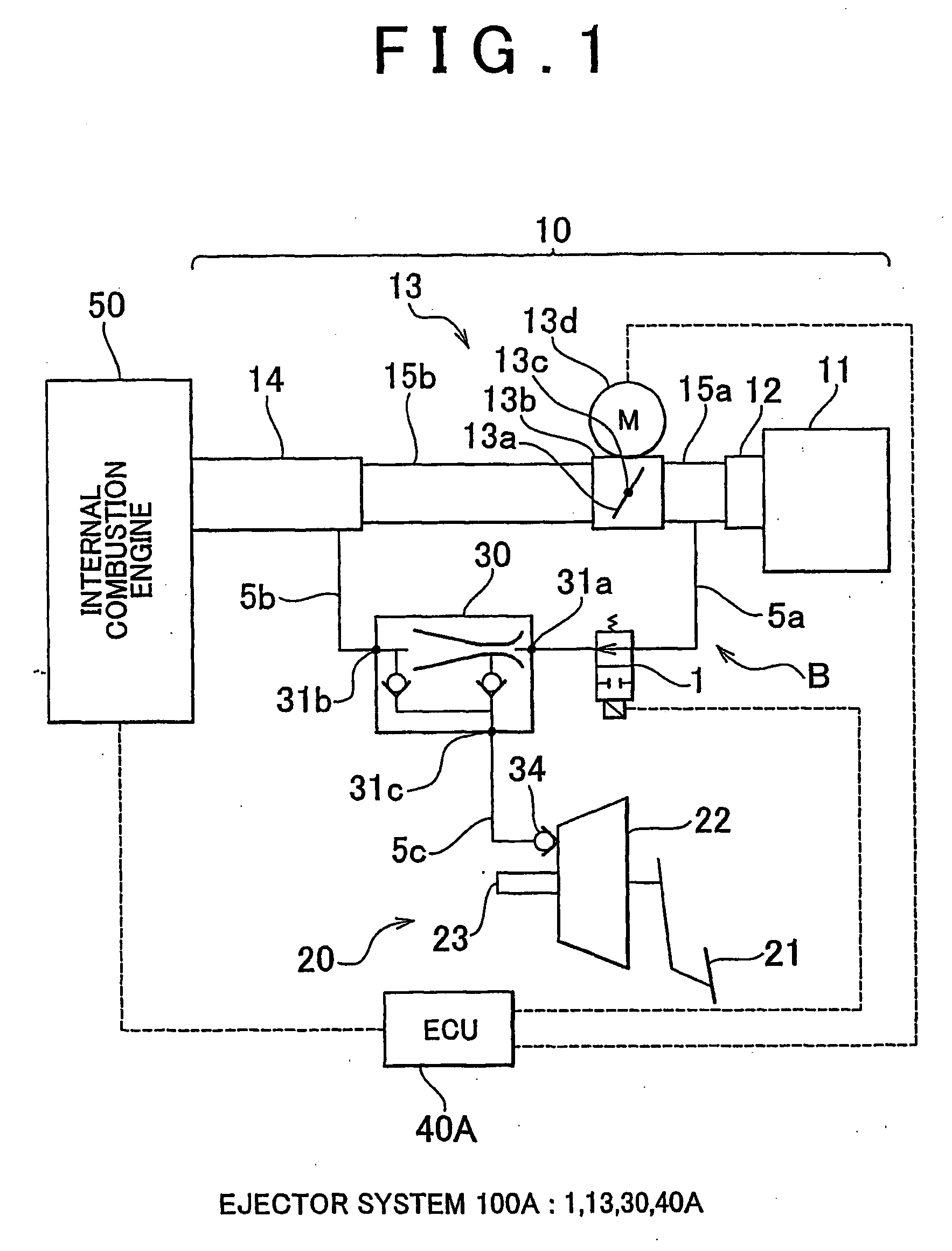
[0011]According to a first aspect of the present invention an vehicle ejector system having an ejector that generates a negative pressure that is greater than the negative pressure to be applied from an air intake passage of the intake system, which provides communication between the
atmosphere and each cylinder of the internal combustion engine, and that supplies the negative pressure to a brake booster, an operation state changing device that either causes the ejector to operate or stop, and a controller that controls the operation state changing device, wherein when fuel is not injected in a combustion cycle of the internal combustion engine, the controller controls the operation state changing device to operate the ejector. That is, in the present invention, when fuel is not injected in the combustion cycle of the internal combustion engine, which is regarded as no
adverse effect on the air-fuel ratio, the ejector is operated. Thus, the ejector is not only operated according to its originally desired operation but also operated during other times. In accordance with this aspect, it is possible to increase the amount of time when the intake air flows through the ejector without adversely affecting the air-fuel ratio. Thus, it is possible to inhibit the blockage of the ejector even if there is a time when the ejector does not operate during operation of the internal combustion engine. According to the above-noted aspect, because there is only a change in the control, it is possible to inhibit the blockage of the ejector with a low cost.
[0012]In a second aspect of the present invention, the operation state changing device may be controlled to operate the ejector when a fuel
cut control of the internal combustion engine is executed. If the ejector is operated when the fuel
cut control is executed as in the above-noted aspect, it is possible to increase the amount of time when the intake air flows through the ejector.
[0013]In a third aspect of the present invention, the operation state changing device may be controlled to operate the ejector when the
ignition switch is off and the internal combustion engine is rotating. That is, even after the
ignition switch is set to off, because the internal combustion engine rotates for some time until it completely stops, it is possible, for example as in the above-noted aspect, to have intake air flow through the ejector. According to the above-noted aspect, it is possible after the internal combustion engine stops to inhibit the blockage of the ejector that can occur resulting from the freezing of
condensed water accumulated in the narrowed passage, and to inhibit deposits generated and fixed on the walls of the passage to aggravate the blockage of the ejector.
[0014]In a fourth aspect of the present invention, when the internal combustion engine is mounted in a
hybrid vehicle that uses an
electric motor as well as the internal combustion engine as a drive power source, and the operation state changing device may be controlled to operate the ejector when the drive power source is switched from the internal combustion engine to the
electric motor. For example, in a so-called
hybrid vehicle as well, using the above-noted aspect it is possible to inhibit the blockage of the ejector.
[0016]According to this aspect, it is possible to provide a low-cost ejector system and a controller that inhibit the blockage of the ejector and adverse affect on the air-fuel ratio even if there is a time when the ejector is not operated.

