
Manual rescue device of lifts

An elevator and manual traction technology, which is applied to elevators, transportation and packaging, elevators and other directions in buildings, can solve the problems of incompatibility, inability to operate, and high battery costs, and achieve the effect of small occupied space, convenient operation and simple structure

Active Publication Date: 2010-05-05
GIANT KONE ELEVATOR CO LTD
View PDF1 Cites 3 Cited by
  • Summary
  • Abstract
  • Description
  • Claims
  • Application Information

AI Technical Summary

Problems solved by technology

[0002] In the prior art, most of the elevators used are machine-room-less elevators mounted on top of the traction machine. However, there are no clear requirements for the manual turning operation of machine-room-less elevators in the existing national standards. Sudden power failure during operation may cause the car to stop on the middle floor and fail to move. At present, most manufacturers use batteries as backup power for emergency power supply, but the cost of batteries is high and regular maintenance is required
The Chinese patent with the patent number CN00241548.8 discloses a manual barring device for a toothless traction machine. By adding a pair of gear pairs to the traction machine, it can be turned by turning the set hand wheel in the event of a power failure. Drive the gear pair to drive the traction machine to rotate, but the maintenance personnel of this kind of device need to enter the hoistway to operate, and the handwheel needs to occupy a certain space. is not suitable

Method used


Image

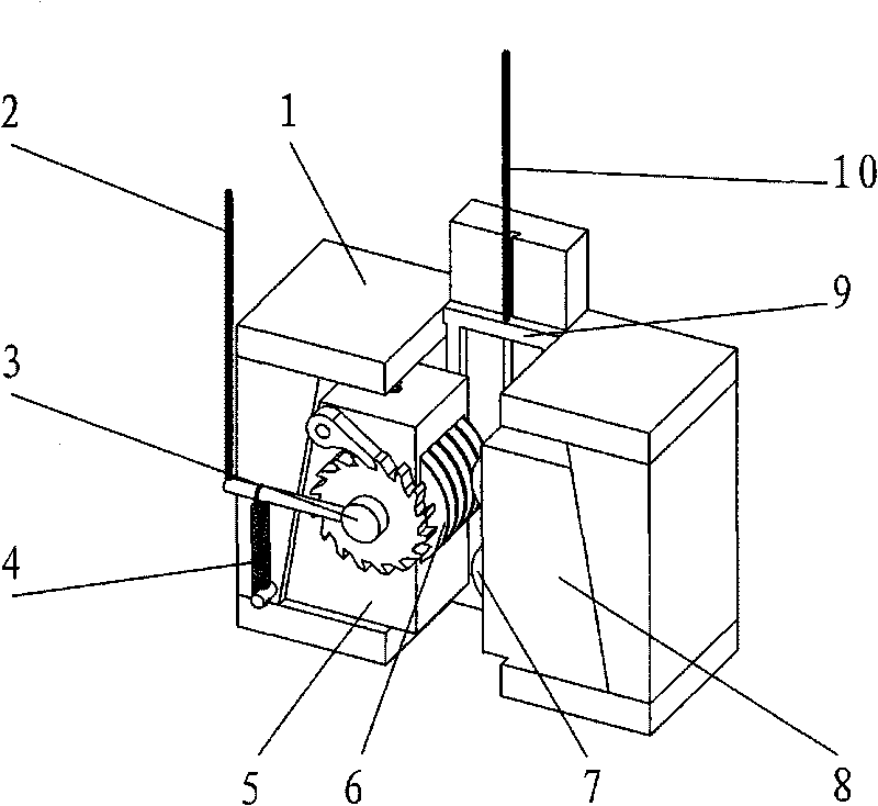
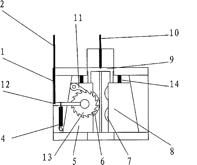
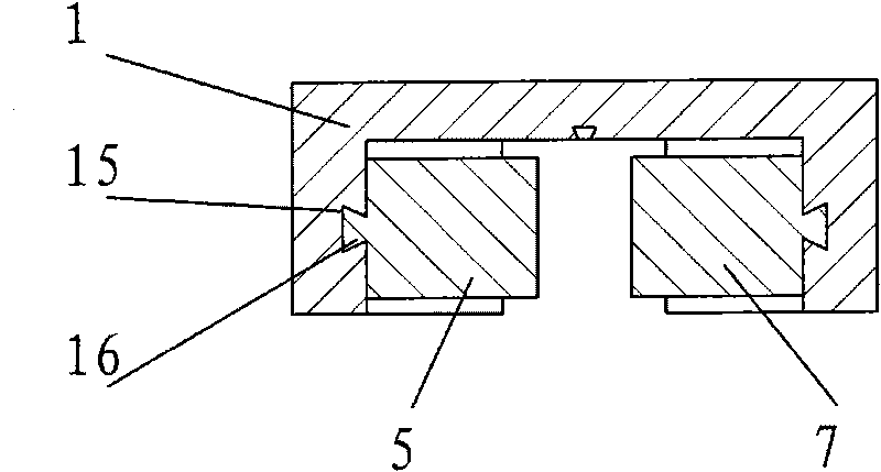
  • Manual rescue device of lifts
  • Manual rescue device of lifts
  • Manual rescue device of lifts

Examples


Embodiment Construction

[0018] The present invention will be described in further detail below in conjunction with the accompanying drawings.

[0019] This specific embodiment is only an explanation of the present invention, and it is not a limitation of the present invention. Those skilled in the art can make modifications to this embodiment without creative contribution as required after reading this specification, but as long as they are within the rights of the present invention All claims are protected by patent law.

[0020] Such as Figure 1-3 As shown, a manual rescue device for an elevator includes: a fixed seat 1, a left wedge 5, a right wedge 8, a manual traction device 3, a lifting member 9, and driving wheels respectively arranged on the left wedge 5 6 and the two driven wheels 7 arranged on the right wedge 8, the fixed seat 1 has an isosceles trapezoidal cavity with openings at the upper and lower ends, on the two hypotenuses of the isosceles trapezoidal cavity of the fixed seat 1 A d...


PUM


Abstract

The invention relates to a manual rescue device of lifts, which comprises a fixed base, a left wedge block, a right wedge block, a manual traction device, a pull-up member, a hoist rope, a driving wheel arranged on the left wedge block and a driven wheel arranged on the right wedge block, wherein the fixed base is provided with a trapezoidal hollow cavity, the left wedge block and the right wedge block are distributed inside the trapezoidal hollow cavity of the fixed base and respectively come into contact with two sides of the trapezoidal hollow cavity, the pull-up member is connected with the left and right wedge blocks and is provided with a primary drag rope, the hoist rope passes through a longitudinal gap therein, which is arranged between the driving wheel and the driven wheel; and the manual traction device comprises: a rocker, a rocker return spring, a pawl and an outer ratchet wheel, wherein the outer ratchet wheel and the driving wheel on the left wedge block are immovably connected to the same shaft and the rocker is also provided with a secondary drag rope. When the hoist rope is clamped by the driving wheel and the driven wheel, the driving wheel is driven by the manual traction device to rotate, as a result, the movement of the hoist rope towards one side can be accomplished in order to drive the lift car.

Description

technical field [0001] The invention relates to a manual rescue device for an elevator, in particular to an overhead manual rescue device for an elevator without a machine room, which is an accessory device of the elevator. Background technique [0002] In the prior art, most of the elevators used are machine-room-less elevators mounted on top of the traction machine. However, there are no clear requirements for the manual turning operation of machine-room-less elevators in the existing national standards. Sudden power failure during operation will cause the car to stop on the middle floor and fail to move. At present, most manufacturers use batteries as backup power for emergency power supply, but the cost of batteries is high and regular maintenance is required. The Chinese patent with the patent number CN00241548.8 discloses a manual barring device for a toothless traction machine. By adding a pair of gear pairs to the traction machine, it can be turned by turning the set...

Claims


Application Information

Patent Timeline
IPC IPC(8): B66B11/04B66B5/00
Inventor 黄文聘叶佳芳高云龙张正华沈国华
Owner GIANT KONE ELEVATOR CO LTD
Learn More