Grating type trenchless prop excavating equipment and trenchless prop method tunnel excavating process

A non-excavation and grating technology, applied in mining equipment, tunnels, earthwork drilling and mining, etc., can solve problems such as easy formation of cavities, complicated cutterhead replacement, roof collapse, etc., to reduce adverse effects, reduce safety risks, eliminate void effect

Inactive Publication Date: 2012-09-05
郭壮
View PDF0 Cites 0 Cited by
  • Summary
  • Abstract
  • Description
  • Claims
  • Application Information

AI Technical Summary

Problems solved by technology

[0002] With the rapid development of my country's railway construction, there are more and more non-open excavation tunnel projects descending across the railway line. For these scattered small (0.8-3.0m diameter culvert) projects, rail beams, I-beams and military beams are used to reinforce the line and carry out jacking construction. According to normal conditions, each site construction needs to block the line at least five times. During the construction period, the train must run at a speed limit of 25-45 km / h, especially on the line Manual excavation of the piles of the pier buttress holes directly destroys the stability of the roadbed and affects the order of railway transportation and safe production
[0003] For tunnel projects with a long length, there is also a construction method using a rotary cutterhead tunnel boring machine, but it is complicated and difficult to replace the cutterhead during construction. Hollow, leading to roof collapse; in case of sudden obstacles or changes in the soil, the cutter head cannot rotate and cut, or even damage the cutter head; deviations are easy to occur during the excavation process, and the deviation needs to be corrected frequently. After the deviation is corrected, the pipe will form a gap with the soil, resulting The body is easy to sink; the diameter of the cutter head is larger than that of the pipe body, which will cause gaps, and pushing the pipe for a long time will cause the soil to subside

Method used


Image

  • Grating type trenchless prop excavating equipment and trenchless prop method tunnel excavating process
  • Grating type trenchless prop excavating equipment and trenchless prop method tunnel excavating process
  • Grating type trenchless prop excavating equipment and trenchless prop method tunnel excavating process

Examples


Embodiment 1

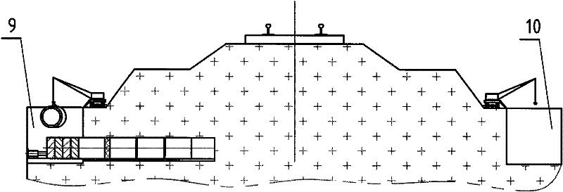
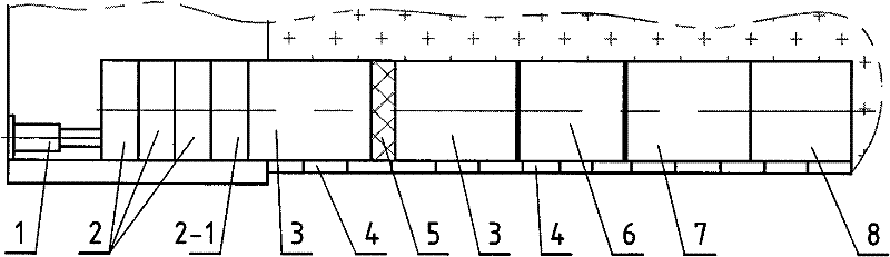
[0046] Example 1 as Figure 1-10 Shown: a grid-type trenchless pipe jacking equipment, including pipe jacking cylinder 1 and its hydraulic station, concrete pipe 3 and crane, and also includes circular outer jacking iron 2, sheath 5, and pipe jacking force The device 6, the guiding concrete pipe 7, the working head 8 for grid top punching and the guide rail 4 arranged under the working head 8 for grid top punching.

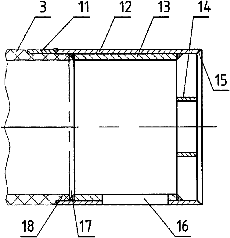
[0047] The grid top punching working head 8 is composed of a top punch outer ring 12, a top punch inner ring 13 and a grid 14 welded together, and the outer diameter of the top punch outer ring 12 is equal to the outer diameter of the concrete pipe 3. The inner diameter of the top punch inner ring 13 is equal to the inner diameter of the concrete pipe 3; one end surface of the top punch outer ring 12 perpendicular to the axis is provided with a knife edge 15, and the grid 14 is connected to the inner side of the top punch outer ring 12 with a knife edge and the to...

Embodiment 2

[0053] Example 2 as Figure 11-12 Shown: piston rod top iron 21, oil cylinder top iron 24, circular outer top iron 2 or the flat joint of concrete pipe 3 end faces include a conical flat joint with a sealing ring 29 at one end and a flat joint with a steel ring 28 at the other end, The outer diameter of the steel ring 28 is equal to the outer diameter of the concrete pipe 3 , and the inner diameter of the steel ring 28 is matched with the conical flat mouth joint with the sealing ring 29 .

Embodiment 3

[0054] Example 3 as Figure 5 Shown: the forward punch type top punch working head 20 is made up of the forward punch type top punch outer ring 19 , the top punch inner ring 13 and the grid 14 which are welded together, and the grid 14 may not be assembled. One end face of the front punch top punch outer ring 19 and the axis at an angle of α = 60° is provided with a knife edge 15, the grid 14 and the inner side of the front punch top punch outer ring 19 with a knife edge end and the top punch inner ring 13 The ends are welded as a whole; the other end of the forward-type top punch outer ring 19 and the top punch inner ring 13 perpendicular to the axis forms a concave groove 17, and the concave groove 17 is connected with the guide concrete pipe 7. Concrete convex groove 18 cooperates socket. The front punch type top punch working head 20 is not provided with the transparent rectangular window 16 described in Embodiment 1, and the guide rail 4 can be laid under the protection ...


PUM


Abstract

The invention relates to a grating type trenchless prop excavating device and a trenchless prop method tunnel excavating process. The grating type trenchless prop excavating device comprises a prop oil cylinder, a hydraulic station of the prop oil cylinder, a concrete pipe, a hoist, outer push iron, a jacket, a guide concrete pipe, a prop stressing device, a grating prop working head or a forwardtype prop working head and a guide rail, wherein the guide rail is arranged under the grating prop working head or the forward type prop working head; the grating prop working head comprises a prop head outer ring, a prop head inner ring and a grating which are welded into a whole; one end surface of the prop head outer ring is provided with a knife edge, and the bottom of the prop head is provided with a translucent window through which the guide rail can pass; and the prop stressing device comprises oil cylinder prop iron, an stressing oil cylinder and piston rod prop iron. The invention issuitable for trenchless excavating tunnels passing through a railway, a highway, an ancient building, a vegetation protecting layer or a rivulet and can effectively control the slide and collapse of the soil layer of an operating surface, reduce the deformation of the surface of the earth and achieve the aim of safe, efficient, civil and environmental-friendly construction.

Description

technical field [0001] The invention relates to an excavation equipment and method for excavating a non-open-pit tunnel, in particular to a grid-type non-excavation pipe jacking equipment and a non-excavation top-punching method tunnel excavation process. Background technique [0002] With the rapid development of my country's railway construction, there are more and more non-open excavation tunnel projects descending across the railway line. For these scattered small (0.8-3.0m diameter culvert) projects, rail beams, I-beams and military beams are used to reinforce the line and carry out jacking construction. According to normal conditions, each site construction needs to block the line at least five times. During the construction period, the train must run at a speed limit of 25-45 km / h, especially on the line Manual excavation of the pier hole piles directly destroys the stability of the roadbed and affects the order of railway transportation and safe production. [0003] F...

Claims


Application Information

Patent Timeline
Patent Type & Authority Patents(China)
IPC IPC(8): E21D9/06
Inventor 郭壮
Owner 郭壮
Why Eureka
Try Eureka