Frequency-modulation electronic ballast for dimmable fluorescent lamp

A technology of electronic ballasts and fluorescent lamps, which is applied in the direction of high-efficiency power electronic conversion, light sources, electric light sources, etc., can solve the problems of EMI radiation, affecting circuit and power factors, and inability to guarantee power switching tubes when adding electronic ballasts, etc., to achieve The effect of simple overall structure and high power factor

Inactive Publication Date: 2010-05-05
HANGZHOU EBOYLAMP ELECTRONICS CO LTD
View PDF0 Cites 23 Cited by
  • Summary
  • Abstract
  • Description
  • Claims
  • Application Information

AI Technical Summary

Problems solved by technology

However, the commonly used methods are as follows: First, use the thyristor to control the chopping control of the AC input mains current, or connect the thyristor in series in the lamp branch circuit to perform chopping control on the lamp current. Although this method realizes It is relatively simple, but it affects the circuit and power factor, and the dimming range is limited; second, the pulse duty ratio dimming method, which realizes the output power by adjusting the pulse ratio of the power switch tube in the high frequency inverter. For example, the FMS7401 of FAIRCHILD Company and the L6574 of ST Company are both control integrated circuits with pulse duty cycle dimming function. If the duty cycle is too small, it will not be possible to ensure that the power switch tube works in the ZVS state, which reduces the reliability of the electronic ballast circuit and increases the EMI radiation of the electronic ballast.

Method used


Image

  • Frequency-modulation electronic ballast for dimmable fluorescent lamp
  • Frequency-modulation electronic ballast for dimmable fluorescent lamp
  • Frequency-modulation electronic ballast for dimmable fluorescent lamp

Examples


Embodiment Construction

[0017] Below in conjunction with accompanying drawing and specific embodiment the present invention is described in further detail:

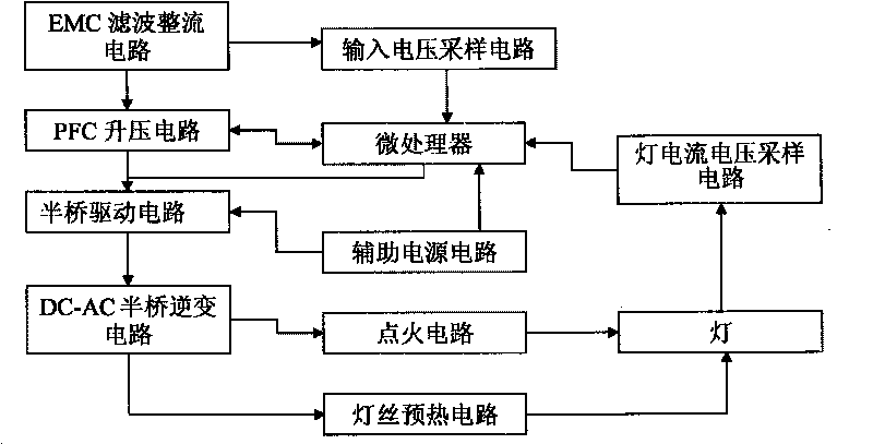
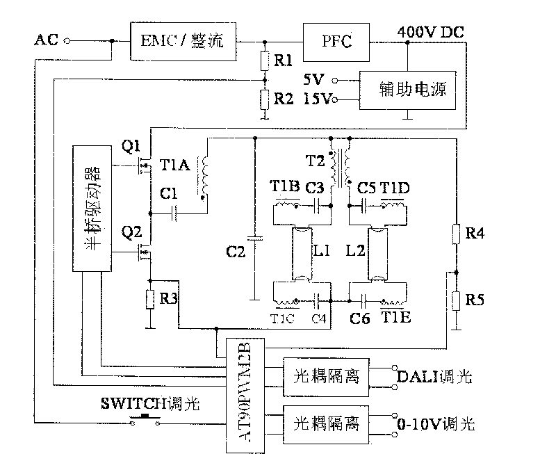
[0018] like figure 1 , 2 As shown, the electronic ballast for frequency-modulated dimmable fluorescent lamps of the present invention includes an EMC filter rectifier circuit, an input voltage sampling circuit, a PFC boost circuit, a half-bridge drive circuit, a DC-AC half-bridge inverter circuit, a micro Processor, lamp current lamp voltage sampling circuit. The EMC filter rectifier circuit is connected to the PFC boost circuit, the half-bridge drive circuit is connected to the DC-AC half-bridge inverter circuit, the lamp current lamp voltage sampling circuit is connected to the microprocessor, and the input voltage sampling circuit is connected to the microprocessor . The electronic ballast for frequency-modulated dimmable fluorescent lamps of the present invention also includes an auxiliary power supply circuit, and both the microprocessor...


PUM


Abstract

The invention relates to a frequency-modulation electronic ballast for a dimmable fluorescent lamp, comprising an EMC filter rectifier circuit, an input voltage sampling circuit, a PFC booster circuit, a half-bridge driver circuit, a DC-AC half-bridge inverter circuit, an ignition circuit, a microprocessor and a lamp current/voltage sampling circuit; the EMC filter rectifier circuit is connected with the PFC booster circuit; the PFC booster circuit is connected with the half-bridge driver circuit and the microprocessor; the half-bridge driver circuit is connected with the DC-AC half-bridge inverter circuit; the DC-AC half-bridge inverter circuit is connected with the ignition circuit; and the lamp current/voltage sampling circuit is connected with the microprocessor. The invention has the following advantages: the electronic ballast dose not use special integrated control circuit but universal microcontroller so as to perform the functions thereof through pulse frequency modulation dimming method, thus the whole structure is simple, and various dimming interfaces can be expanded conveniently to perform digital dimming.

Description

technical field [0001] The invention relates to an electronic ballast, in particular to a two-stage half-bridge mode, which realizes stepless smooth dimming within a wide power range by adjusting the DC-AC half-bridge inverter frequency. Background technique [0002] With the improvement of people's requirements for lighting quality, traditional fixed brightness fluorescent lamps can no longer meet people's needs for changing visual effects, and are not conducive to saving energy. The appearance of dimmable high-frequency fluorescent lamps not only meets people's need to change visual effects, but also achieves the purpose of energy saving. However, the commonly used methods are as follows: First, use the thyristor to control the chopping control of the AC input mains current, or connect the thyristor in series in the lamp branch circuit to perform chopping control on the lamp current. Although this method realizes It is relatively simple, but it affects the circuit and pow...

Claims


Application Information

Patent Timeline
Patent Type & Authority Applications(China)
IPC IPC(8): H05B41/392H05B41/14H02M5/458
CPCY02B70/10
Inventor 章剑雄唐耀宗石航波来佳立
Owner HANGZHOU EBOYLAMP ELECTRONICS CO LTD
Why Eureka
Try Eureka