Sealing device for drive mechanism of horizontal centrifuge

A horizontal centrifuge and sealing device technology, applied in the direction of engine sealing, engine components, mechanical equipment, etc., can solve the problems of affecting the lubrication effect, the decline of bearing lubrication quality, and the decline of lubricating oil quality, so as to improve the shielding effect, The effect of guaranteeing the lubrication effect

Active Publication Date: 2010-05-12
JIANGSU PEONY CENTRIFUGE MFG
View PDF0 Cites 6 Cited by
  • Summary
  • Abstract
  • Description
  • Claims
  • Application Information

AI Technical Summary

Problems solved by technology

At present, many high-speed centrifuges use thin oil lubrication, which can increase the limit drum speed of the bearing, thereby improving the performance of the centrifuge; at the same time, because the limit line speed of the skeleton oil seal is generally 12-14m/s , cannot meet the requirements of high-speed centrifuges. In order to increase the speed of the centrifuge, try to use a labyrinth seal at the bearing. The oil enters the oil tank, and there is no protection against forei

Method used


Image

  • Sealing device for drive mechanism of horizontal centrifuge
  • Sealing device for drive mechanism of horizontal centrifuge
  • Sealing device for drive mechanism of horizontal centrifuge

Examples


Embodiment Construction

[0011] Specific embodiments of the present invention will be described in detail below in conjunction with the accompanying drawings.

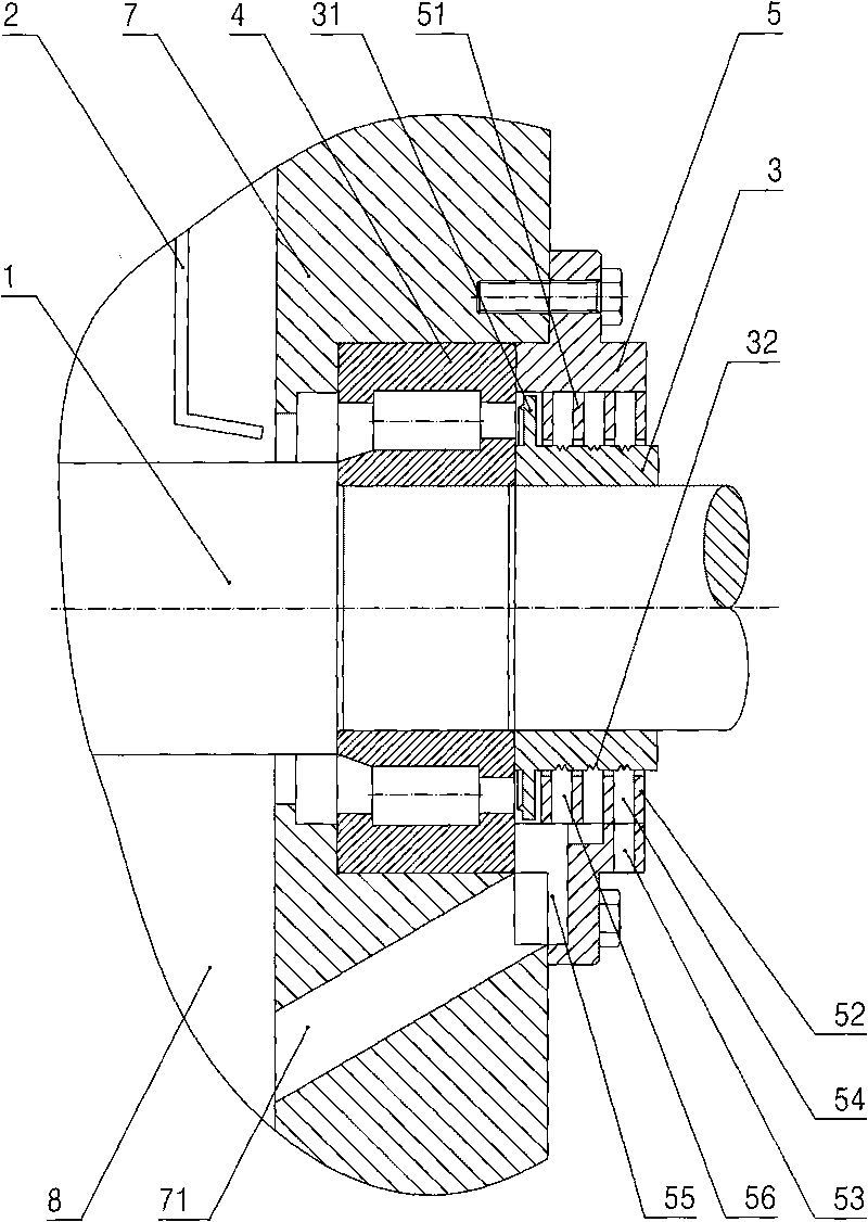
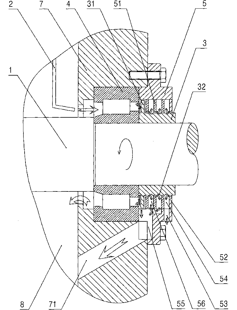
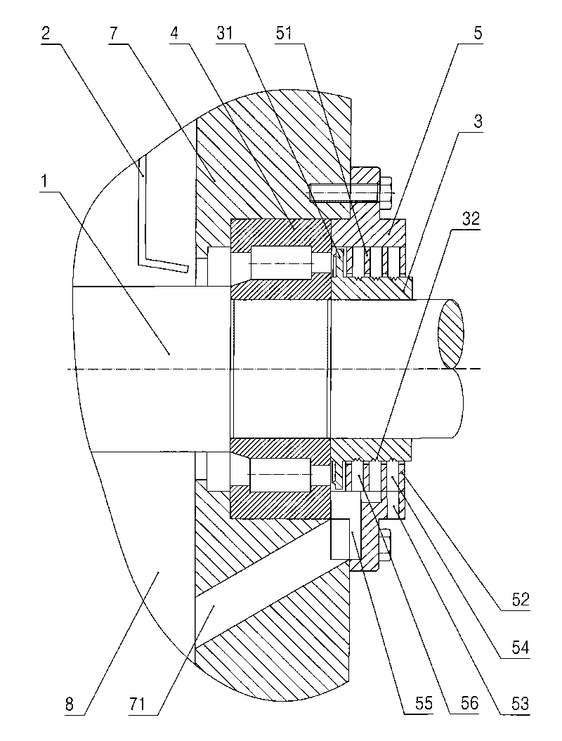
[0012] Such as figure 1 As shown, the sealing device of the transmission mechanism in the horizontal centrifuge according to the present invention includes: a bearing seat 7 arranged on the frame, a bearing 4 arranged in the bearing seat 7 and a gland 5 arranged outside the bearing 4 , the bearing seat 7 is provided with an oil return groove 71, the bearing 4 is pierced with a main shaft 1, the main shaft 1 passes through the gland 5, and a sealing sleeve 3 is provided between the gland 5 and the main shaft 1—the sealing sleeve 3 is set on On the main shaft 1, the inner side of the sealing sleeve 3 is provided with a main retaining ring 31, and the inner wall of the gland 5 is provided with a leak-proof ring 52 and three secondary retaining rings 51, the leak-proof ring 52 is located on the outermost side, and the main retaining ring 31 and pr...


PUM


Abstract

The invention discloses a sealing device for a drive mechanism of a horizontal centrifuge, which can prevent foreign liquid from entering an oil tank and recover a small amount of lubricating oil, and comprises a bearing seat arranged on a rack, a bearing arranged in the bearing seat and a gland arranged at the outer side of the bearing, wherein the bearing seat is internally provided with an oil returning slot; a main shaft is arranged in the bearing in a penetrating way and penetrates through the gland; a sealing case is arranged between the gland and the main shaft; a main baffle ring is arranged at the inner side of the sealing case; a leakage-proof ring and at least two subsidiary baffle rings are arranged on the inner wall of the gland; the leakage-proof ring is arranged at the outermost part; gaps are respectively arranged between the main baffle ring and the gland, the leakage-proof ring and the sealing case, and the subsidiary baffle rings and the sealing case; a liquid stopping trough is formed between the leakage-proof ring and the adjacent subsidiary baffle ring thereof; the liquid stopping trough is communicated with the liquid returning slot arranged at the outer side of the gland; an oil stopping groove is formed between two adjacent subsidiary baffle rings; and the oil stopping groove is communicated with the oil returning slot by an oil returning channel arranged at the inner side of the gland. The sealing device is mainly used in a high-speed horizontal centrifuge.

Description

technical field [0001] The invention relates to a horizontal centrifuge, in particular to a sealing device for a transmission mechanism in the horizontal centrifuge. Background technique [0002] As we all know, a centrifuge is a machine that uses the inertial centrifugal force generated by the rotation of the drum to separate or concentrate suspensions, emulsions and other heterogeneous materials. According to the transmission structure, the centrifuges are mainly divided into two types: vertical and horizontal. The main shaft of the horizontal centrifuge is placed horizontally, and its transmission mechanism must have at least two sets of bearings. Centrifuges that are heavy and rotate at high speeds, especially fully automatic continuous centrifuges, have very high requirements for the lubrication of bearings. At present, many high-speed centrifuges use thin oil lubrication, which can increase the limit drum speed of the bearing, thereby improving the performance of the ...

Claims


Application Information

Patent Timeline
IPC IPC(8): F16J15/16
Inventor 顾济林张威程积涛杨善成
Owner JIANGSU PEONY CENTRIFUGE MFG
Why Eureka
Try Eureka