Hole plug

A hole plug and leg technology, which is used in gas/liquid distribution and storage, pressure vessels, superstructures, etc., can solve problems such as the loss of freedom of hole plug design, difficulty in ensuring high water resistance, and hindering miniaturization. Simple structure, improved water resistance, and the effect of reducing load

Inactive Publication Date: 2010-05-26
NIFCO INC
View PDF8 Cites 10 Cited by
  • Summary
  • Abstract
  • Description
  • Claims
  • Application Information

AI Technical Summary

Problems solved by technology

However, the corrugated support part needs to ensure a relatively large dimension in the longitudinal direction in order to perform its function. Therefore, the interval between the standing plate part and the pillar part also needs to be wide enough to accommodate the support part. Therefore, there is a problem of plug design. issues such as compromised degrees of freedom and obstacles to its miniaturization
In addition, in the prior art of Patent Document 2, since a plurality of standing plate portions closely contacting the inner peripheral surface of the hole of the plate-shaped member are arranged at predetermined intervals in the circumferential direction, it is difficult to ensure high insulation. water problem

Method used


Image

  • Hole plug
  • Hole plug
  • Hole plug

Examples


Embodiment Construction

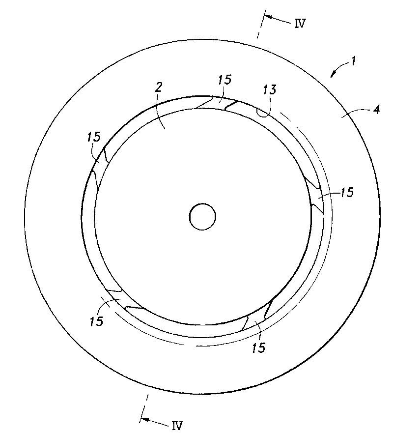
[0026] Embodiments of the present invention will be described below with reference to the drawings. In the following, unless otherwise specified, the terms "up" and "down" indicating directions are in accordance with Figure 4 The orientation of the plug 1 is shown (ie, the head 2 side is the upper side and the leg 3 side is the lower side).

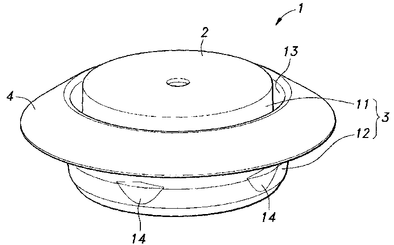
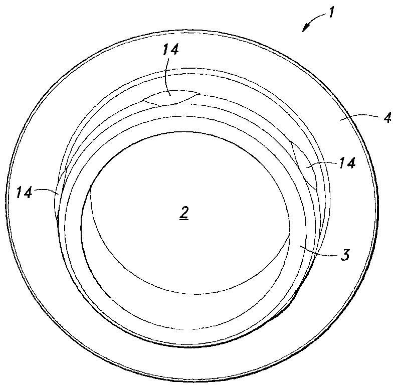
[0027] figure 1 and figure 2 are perspective views of the hole plug of the present invention observed from the upper side and the lower side, respectively, image 3 is the top view of hole plug, Figure 4 is along image 3 Partial sectional view of line IV-IV in, Figure 5 It is a partial enlarged view showing the detailed structure of locking claws and ribs. and, Figure 5 Shows the structure of the plug viewed from the bottom.

[0028] Such as figure 1 and figure 2 As shown, the hole plug 1 is used to close the hole 22 (refer to Image 6 ) includes a head 2 made of a circular flat plate, a leg 3 protruding downward from th...


PUM


Abstract

A hole plug, wherein the hole plug is configured so as to withstand a high pulling force and so that a load acting on an engaging claw when the hole plug is separated from a mold is reduced. A leg (3) of a hole plug (1) is provided with an inner tube (11), an outer tube (12) surrounding the inner tube, a rib (15) interconnecting the inner and outer tubes, and an engaging claw (14) provided to theouter peripheral surface of the outer tube and engaged with the peripheral edge of the leg when the leg is inserted in a hole (22) in a body panel (21). The rib is provided to a position corresponding to the position of the engaging claw and is tilted relative to the radial direction of the hole plug when viewed in the direction of insertion of the leg.

Description

technical field [0001] The present invention relates to a hole plug for closing a hole provided in a plate-shaped member such as a body panel of an automobile. Background technique [0002] Conventionally, holes used for work and inspection, wiring of wire harnesses, etc., and mounting of components have been provided in the body panels of automobiles. When these holes are not in use, they are generally closed with resin plugs to prevent entry of water or the like. Various technologies have been developed for the hole plug for the purpose of improving mounting workability, water-proof (waterproof) performance, and the like. [0003] For example, known plugs are provided with an insertion portion provided with a blind hole in the center and locking claws engaged with the mounting holes on the entire periphery, and a non-insertion portion connected to the upper end of the insertion portion; the insertion portion There is an annular arc-shaped groove provided on the periphery...

Claims


Application Information

Patent Timeline
Patent Type & Authority Applications(China)
IPC IPC(8): B62D25/12
CPCB60R16/0222B62D25/24F16J13/14
Inventor 泷田高志
Owner NIFCO INC
Why Eureka
Try Eureka