Rivet

A technology of rivets and rivet caps, applied in rivets and other directions, can solve problems such as uneven force, uneven flanging, and affecting riveting strength

Inactive Publication Date: 2010-05-26
CAMA JIAHUA LUOYANG NEW ENERGY
View PDF0 Cites 4 Cited by
  • Summary
  • Abstract
  • Description
  • Claims
  • Application Information

AI Technical Summary

Problems solved by technology

However, this type of rivet has a simple structure and is prone to uneven force during flanging, resulting in uneven flanging and affecting the strength of the riveting, and the sharp openings produced by the flanging are likely to cause damage to personnel

Method used


Image

  • Rivet
  • Rivet
  • Rivet

Examples


Embodiment 1

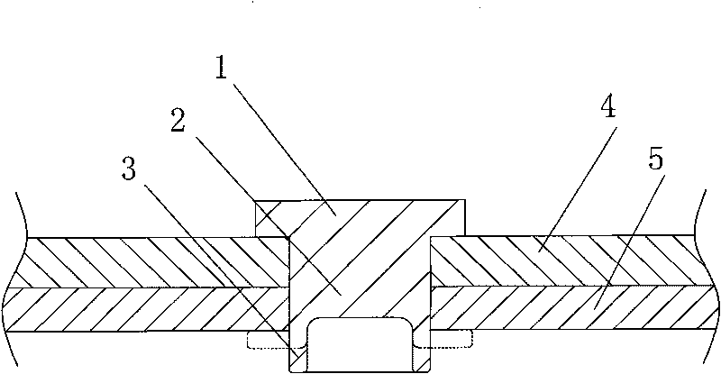
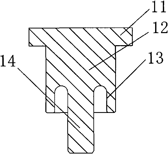
[0015] Such as figure 2 As shown, the rivet of this embodiment includes a cylindrical rivet body 12 with a rivet cap 11 at one end, and a hollow flanging structure at the other end of the rivet body away from the rivet cap, and the flanging structure is arranged on the rivet The axial groove 13 at the end of the body, the groove wall of the groove 13 is used for flanging and riveting; the end of the rivet body away from the rivet cap is also provided with a guide post 14 coaxial with the rivet body, the guide The posts 14 are arranged in the groove 13 at intervals, one end of the guide post 14 is fixedly connected to the bottom of the groove 13 , and the other end protrudes from the notch of the groove 13 .

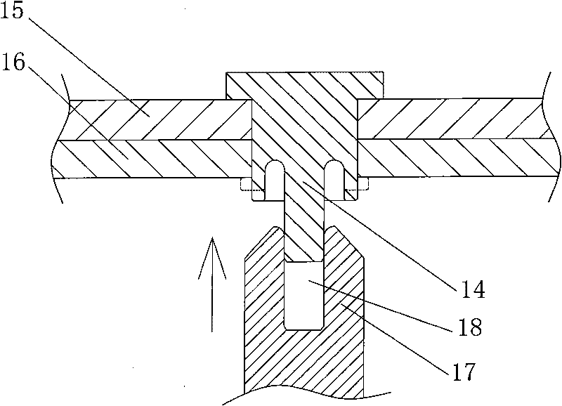
[0016] When the rivet of this embodiment is in use, such as image 3 As shown, the rivet body is first inserted into the riveting holes of the riveting fasteners 15, 16, so that the rivet cap is pressed against one of the riveting fasteners 15, and then the flanging str...

Embodiment 2

[0018] Such as Figure 5 As shown, the structure of the rivet of this embodiment is the same as that of Embodiment 1, the difference lies in that a thread 20 is provided on the outer peripheral surface of the guide post 14 of the rivet. The method of using the rivet in this embodiment is the same as in Embodiment 1, the difference is that a safety nut 19 can be screwed on the guide post 14 after flanging treatment, which not only increases the riveting strength, but also prevents the groove wall from flanging The resulting sharp openings will cause damage to personnel.

Embodiment 3

[0020] The structure of the rivet in this embodiment is the same as that in Embodiment 1, and can be used in the lead-out structure of the battery or supercapacitor pole, wherein the guide post can be used as the lead-out end of the positive and negative poles of the battery or supercapacitor. Such as Figure 6 As shown, 50 in the figure is an end cover of a battery or a supercapacitor, and a through hole 52 is opened in the center of the end cover 50, and a rivet is inserted upside down in the through hole 52; the rivet body 12 of the rivet and the through hole 51 An insulating sealing sleeve 53 is tightly sealed between the hole walls, and the upper and lower ends of the insulating sealing sleeve 53 protrude from the aperture of the through hole 51 respectively, and the lower end of the insulating sealing sleeve 53 is clamped between the rivet cap 11 and the top cover 50 of the rivet. Between the lower surfaces; a gasket 54 is set on the upper part of the rivet body 12 of th...


PUM


Abstract

The invention discloses a rivet comprising a rivet body with a rivet cap at one end and a hollow turning structure at the other end away from the rivet cap. A guiding post is also arranged at one side of the rivet body with the turning structure which is arranged on the periphery of the guiding post to form a clearance fit with the guiding post; the guiding post and the rivet body are coaxially arranged; and the end of the turning structure extends out of the top end of the turning structure. The invention is provided with the guiding post on the rivet, can guide a turning tool to carry out even turning treatment to the turning structure so that the rivet after the turning treatment has favorable riveting strength and facilitates the turning treatment.

Description

technical field [0001] The invention relates to a rivet. Background technique [0002] There are many types of rivets, commonly used are semi-round head, flat head, countersunk head rivets, blind rivets, and semi-hollow rivets. Among them, semi-hollow rivets are light in weight, weak in nail head, and easy to install, and are used in riveting occasions of non-metallic materials. General semi-tubular rivets such as figure 1 As shown, it includes a rivet body 2 with a rivet cap 1 at one end, and a hollow flange structure 3 at the other end of the rivet body 2 away from the rivet cap 1 . When in use, insert the rivet body into the riveting holes of the riveting fasteners 4 and 5, and then perform flanging treatment on the flanging structure 3 at the end of the rivet body (the dotted line in the figure is the flanging structure after the flanging treatment), which can be achieved with the rivet cap. A tight connection between riveted fasteners. However, this type of rivet ha...

Claims


Application Information

Patent Timeline
Patent Type & Authority Applications(China)
IPC IPC(8): F16B19/04
Inventor 张建锋田晖张永杰孙远李远锋王珂鹏黄伟梁晓鸽
Owner CAMA JIAHUA LUOYANG NEW ENERGY
Why Eureka
Try Eureka